
Fuel Line Installation Details on 1.5L Models
1 - Fuel supply hose (pressure line); 2 - O-ring; 3 - Fuel return hose; 4 - Vacuum hose; 5 - Fuel pressure regulator; 6 - O-ring; 7 - Contact connectors for electrical wiring of injectors; 8 - Fuel line; 9 - Insulating sleeves; 10 - Insulating sleeves; 11 - Injector; 12 - Sealing sleeve; 13 - O-ring
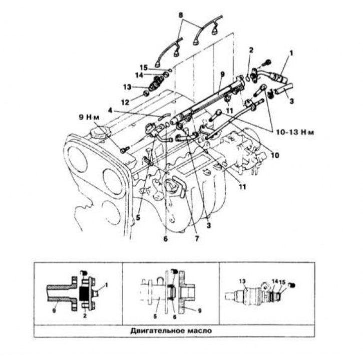
Fuel Line Installation Details on 1.8L Models
1 - Fuel supply hose (pressure line); 2 - O-ring; 3 - Fuel return hose; 4 - Vacuum hose; 5 - Fuel pressure regulator; 6 - O-ring; 7 - PCV hose; 8 - Contact connectors for electrical wiring of injectors; 9 - Fuel line; 10 - Return tube; 11 - Insulating sleeve; 12 - Insulating sleeve; 13 - Injector; 14 - Sealing sleeve; 15 - O-ring
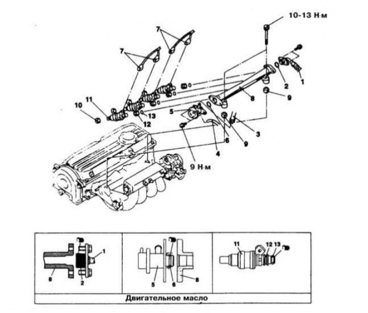
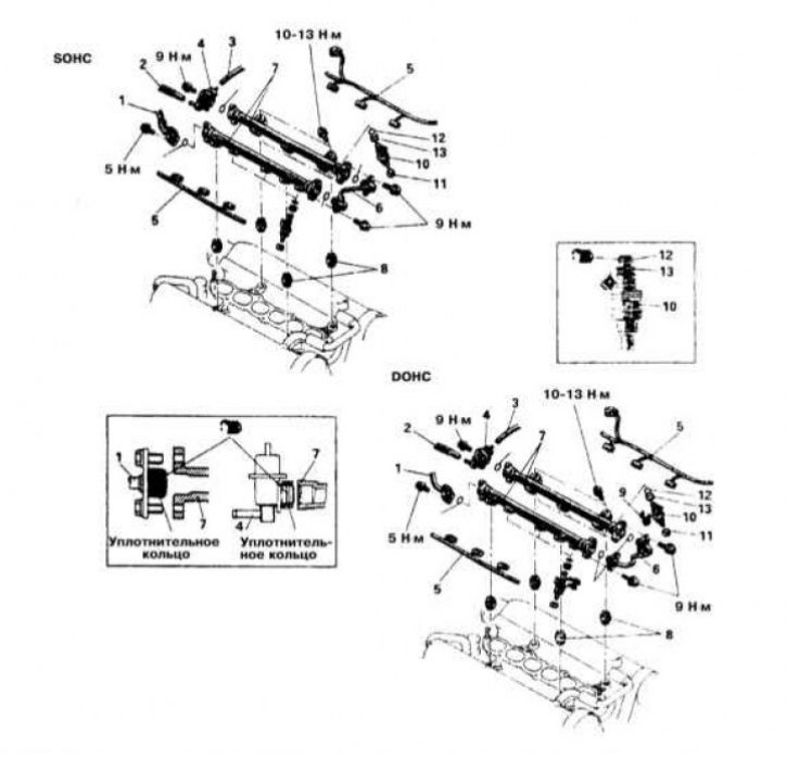
Fuel Line Installation Details on 2.0L SOHC Models
1 - Breather pipe; 2 - PCV hose; 3 - Fuel supply hose (pressure line); 4 - O-ring; 5 - Vacuum hose; 6 - Fuel return hose; 7 - Fuel pressure regulator; 8 - O-ring; 9 - Wiring of injection injectors; 10 - Fuel line; 11 - Insulating sleeves; 12 - Insulating sleeve; 13 - Injector; 14 - O-ring; 15 - Sealing sleeve; N - Replace
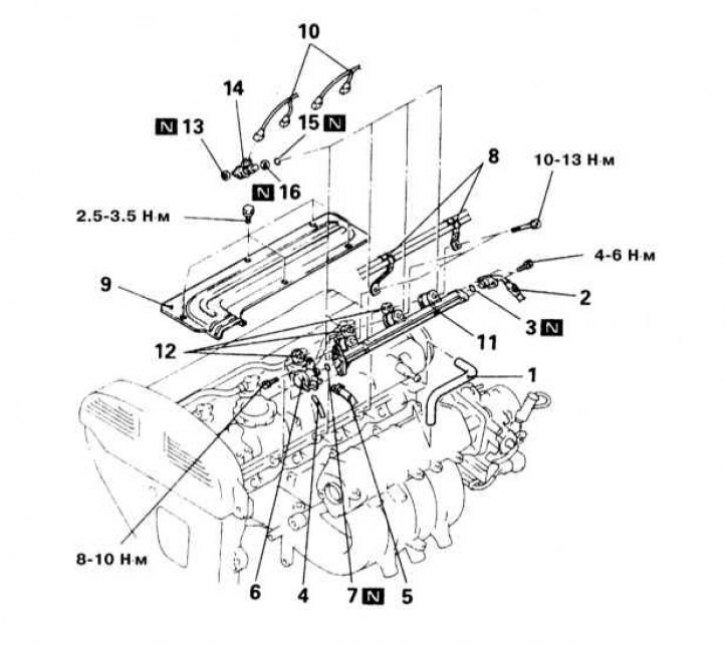
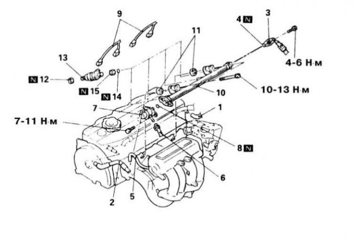
Fuel Line Installation Details on 1.6L and 2.0L DOHC Models
1 - PCV hose; 2 - Fuel supply hose (pressure line); 3 - O-ring; 4 - Vacuum hose; 5 - Fuel return hose; 6 - Fuel pressure regulator; 7 - O-ring; 8 - Intermediate fasteners of the gas cable; 9 - Central cover; 10 - Wiring of injection injectors; 11 - Fuel line; 12 - Insulating sleeve; 13 - Insulating sleeve; 14 - Injector; 15 - O-ring; 16 - Sealing (landing) sleeve; N - Replace
Fuel Line Installation Details on 3.0L Models
1 - Fuel supply hose (pressure line); 2 - Fuel return hose; 3 - Vacuum hose; 4 - Fuel pressure regulator; 5 - Wiring of fuel injection injectors; 6 - Connecting tube; 7 - Assemblies of fuel lines; 8 - Insulating sleeve; 9 - Injector support bracket; 10 - Injector; 11 - Insulating sleeve; 12 - O-ring; 13 - Sealing sleeve
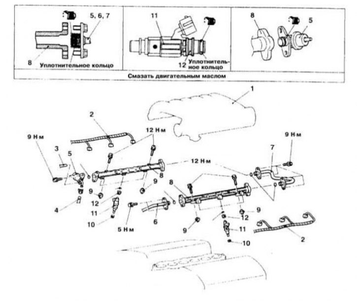
Fuel Line Installation Details on 3.5L Models
1 - equalizing chamber; 2 - Wiring of injectors; 3 - Vacuum hose; 4 - Fuel return hose; 5 - Fuel pressure regulator; 6 - Fuel supply hose (pressure line); 7 - Connecting tube; 8 - Assemblies of fuel lines; 9 - Insulating sleeve; 10 - Insulating sleeve; 11 - Injectors; 12 - Sealing sleeve
Warning! Remember that gasoline is a highly flammable liquid! Observe all applicable fire safety precautions when working on power system components. Do not smoke! Do not approach the place of work with an open flame or carrying an unprotected lampshade! Do not service the system in rooms equipped with natural gas-fired heaters equipped with a pilot flame (such as water heaters and clothes dryers). Do not forget that gasoline is classified as a carcinogen, i.e., substances that contribute to the development of cancer! Try to avoid getting fuel on open areas of the body, use rubber protective gloves, in case of accidental unexpected contact with fuel, thoroughly wash your hands with warm water and soap. Clean up spilled fuel immediately and do not store fuel-soaked rags near open flames. Remember that the fuel injection system of models equipped with fuel injection is constantly under pressure. Relieve any residual pressure in the system before attempting to disconnect fuel lines. Wear safety goggles when servicing power system components. Keep a class B fire extinguisher handy at all times!
Engines 1.5L, 1.8L and 2.0L SOHC
Removing
1. Details of the fuel line installation on the 1.5L, 1.8L and 2.0L SOHC models are shown in the illustrations.
2. Relieve pressure in the supply system (see Section Depressurizing the supply system).
3. Disconnect the PCV hose from the cylinder head cover. On the opposite side of the cover, disconnect the breather pipe.
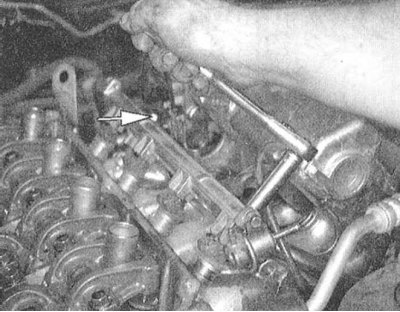
4. Turn out bolts of fastening of a line of giving of fuel (pressure line) and disconnect the latter from the fuel line - get ready to collect the spilled fuel, immediately plug the open ends of the line and fitting to avoid internal contamination of the fuel system path.
5. Remove the vacuum hose from the fuel pressure regulator.
6. Disconnect the return line from the regulator
7. Having previously marked, disconnect the electrical wiring from the fuel injection injectors.
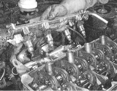
8. Turn out bolts of fastening of assembly of a fuel highway to the inlet pipeline. Carefully lift the line and remove it from the engine - make sure that the injectors do not fall out of the assembly. Transfer the removed assembly to a workbench and wrap the injectors with plastic wrap to keep dirt out.
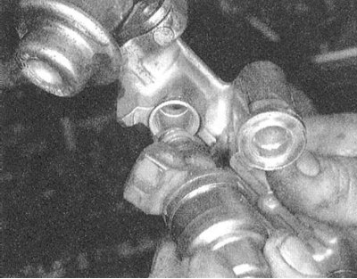
9. Remove the landing insulating bushings of the injectors from the assembly of the inlet pipeline - when assembling the bushings, they must be replaced without fail.
10. Carefully release the injectors from the fuel line assembly with the landing sleeves and o-rings seated on them.
Installation
1. Fit new insulators into each of the injector ports (sealing) bushings.
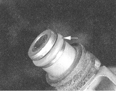
2. Remove the old sealing bushings and sealing rings from the injectors and install new ones in their place.
Note. Before installation, the O-rings should be lightly lubricated with clean engine oil.
3. After replacing the O-ring, install the pressure regulator to the fuel line assembly. Check the freedom of rotation of the regulator, if necessary, remove the regulator and check if the sealing ring is twisted. If everything is in order, achieve the alignment of the holes, screw in the mounting bolts and tighten them with the required force (9 Nm).
Note. This procedure must be carried out even if the fuel line has not been removed.
4. Rotate and translate the injectors into the fuel line. Check the freedom of rotation of the installed injectors, if necessary, remove the corresponding injector and check that the O-ring is not twisted.
5. Install the fuel line assembly in its regular place on the engine, - make sure that each of the injectors correctly enters its receiving socket (with an insulating sleeve planted in it).
6. Screw in the fuel line mounting bolts and tighten them with the required force (12 Nm).
7. Connect to injectors electroconducting.
8. Connect the fuel return hose to the pressure regulator, then connect the vacuum hose.
9. Replacing the O-ring (before installation, the ring should be lubricated with liquid impellent oil), restore the original pressure line connection (fuel lines). Screw in and tighten the fixing bolts.
10. Connect the PCV hose and breather fitting.
11. Connect the negative cable to the battery. Pressurize the system and check the tract for signs of leak development.
1.6L and 2.0L DOHC engines
Removing
1. Details of fuel line installation on 1.6L and 2.0L DOHC models are shown in the illustration.
2. Relieve pressure in the supply system (see Section Depressurizing the supply system).
3. Disconnect the negative cable from the battery.
Attention! If the stereo system installed in the car is equipped with a security code, before disconnecting the battery, make sure that you have the correct combination to activate the audio system!
4. Wrapping the nipple connector with a rag, disconnect the fuel supply hose from the fuel line (pressure line).
5. Disconnect the return line and remove the o-ring from its union connector.
6. Disconnect the vacuum hose from the fuel pressure regulator
7. Disconnect the PCV hose. On 2.0L models, remove the central cover of the unit.
8. Having previously marked, disconnect the electrical wiring from the fuel injection injectors.
9. Turn out bolts of fastening of a fuel highway.
10. Carefully remove the fuel line assembly from the engine - make sure that the rubber mounting bushings do not fall out.
11. Release the injectors from the line - the lower sealing bushings must be replaced without fail.
12. Measure the electrical resistance of each of the injectors. Compare the measurement results with the requirements of the Specifications (2÷3 Ohm [at 20°C] for 2.0L turbocharged engines and 13÷15 Ohm [at 20°C] for other engines).
Installation
1. Install new grommet and o-rings on the injectors
2. Establish injectors on the regular places on a fuel highway.
3. After replacing the mounting sleeves, install the fuel line assembly to the intake manifold. Before tightening the mounting bolts, make sure that all the rubber bushings provided for by the design are present in their seats.
4. Tighten the fixing bolts to the required torque (11 Nm).
5. Connect the electrical wiring to the injectors and install the center cover. Connect the PCV hose.
6. Connect the vacuum hose to the fuel pressure regulator.
7. Connect the fuel return hose.
8. Replacing the O-ring (lubricate the new ring with liquid oil before installation), connect the fuel line (pressure line).
9. Connect the negative cable to the battery. Pressurize the system and check the tract for signs of leak development.
Engines 2.4 l
Removing
1. Relieve the pressure in the supply system (see Section Depressurizing the supply system).
2. Having previously marked, disconnect from the spark plugs and take the electrical wiring to the side of the BB.
3. Disconnect the PCV hose from the cylinder head cover.
4. Turn out bolts of fastening of the pressure head line to a fuel highway. Disconnect line - prepare to collect spilled fuel. Seal the open ends of the line and barb immediately to avoid internal contamination of the power system path.
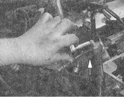 |  |
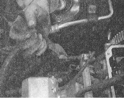 |
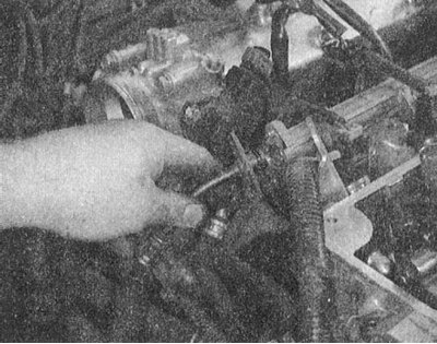
5. Disconnect the vacuum hose and fuel return line from the pressure regulator.
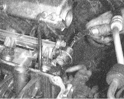 |  |
 |
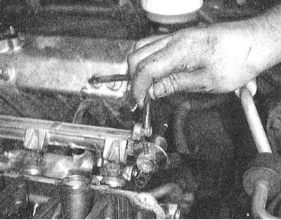
6. Having previously marked, disconnect the electrical wiring from the fuel injection injectors.
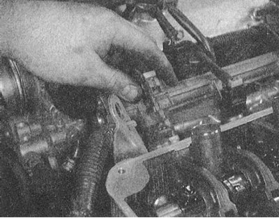
7. Turn out bolts of fastening of assembly of a fuel highway to the inlet pipeline. Carefully lift the line and remove it from the engine - make sure that the injectors do not fall out of the assembly. Transfer the removed assembly to a workbench and wrap the injectors with plastic wrap to keep dirt out.
 |  |
8. Remove the landing insulating bushings of the injectors from the assembly of the inlet pipeline - when assembling the bushings, they must be replaced without fail.
9. Carefully release the injectors from the assembly of the fuel line together with the landing sleeves and sealing rings seated on them - when assembling the rings, they must be replaced without fail.
 |  |
Installation
1. Fit new insulators into each of the injector ports (sealing) bushings.
2. Remove the old sealing bushings and sealing rings from the injectors and install new ones in their place.
Note. Before installation, the O-rings should be lightly lubricated with clean engine oil.
3. After replacing the O-ring, install the pressure regulator to the fuel line assembly. Check the freedom of rotation of the regulator, if necessary, remove the regulator and check if the sealing ring is twisted. If everything is in order, achieve the alignment of the holes, screw in the mounting bolts and tighten them with the required force (9 Nm).
Note. This procedure must be carried out even if the fuel line has not been removed.
4. Rotate and translate the injectors into the fuel line. Check the freedom of rotation of the installed injectors, if necessary, remove the corresponding injector and check that the O-ring is not twisted.
5. Install the fuel line assembly in its regular place on the engine, - make sure that each of the injectors correctly enters its receiving socket (with an insulating sleeve planted in it).
6. Screw in the fuel line mounting bolts and tighten them with the required force (12 Nm).
7. Connect to injectors electroconducting.
8. Connect the fuel return hose to the pressure regulator, then connect the vacuum hose.
9. Replacing the O-ring (before installation, the ring should be lubricated with liquid impellent oil), restore the original pressure line connection (fuel lines). Screw in and tighten to the required torque (6 Nm) fixing bolts.
10. Connect the PCV hose and breather fitting.
11. Connect the negative cable to the battery. Pressurize the system and check the tract for signs of leak development.
Engines 3.0 l and 3.5 l
Removing
1. Details of the fuel line installation on the 3.0L and 3.5L DOHC models are shown in the illustrations.
2. Relieve pressure in the supply system (see Section Depressurizing the supply system).
3. Disconnect the negative cable from the battery.
Attention! If the stereo system installed in the car is equipped with a security code, before disconnecting the battery, make sure that you have the correct combination to activate the audio system!
4. Empty the cooling system (see chapter Settings and ongoing maintenance).
5. Disconnect all components from the intake air path pressure chamber and remove the chamber from the intake manifold assembly (see chapter Power and exhaust systems).
6. Having wrapped the union connector with a rag, disconnect the fuel supply hose from the fuel line (pressure line).
7. Disconnect the return line and remove the o-ring from its union connector.
8. Disconnect the vacuum hose from the fuel pressure regulator
9. Having previously marked, disconnect the electrical wiring from the fuel injection injectors.
10. Remove the tube connecting the fuel lines. Turn out bolts of fastening of assemblies of fuel highways.
11. Carefully remove the fuel line assemblies from the engine - make sure that the rubber mounting bushings do not fall out.
12. Release the injectors from the lines - the lower sealing bushings must be replaced without fail.
Installation
Note. On some models, the injectors are fixed to the line by means of clamps. Don't forget to put the latches in place when assembling.
1. After lubricating with liquid oil, install new insulating sleeves and o-rings on the injectors.
2. Install the injectors in their original locations on the fuel line assemblies.
3. After replacing the landing sleeves, install the fuel line assemblies on the inlet pipeline. Before tightening the mounting bolts, make sure that all the rubber bushings provided for by the design are present in their seats.
4. Tighten the fixing bolts to the required torque (10÷13 Nm).
5. Connect the wiring to the injectors.
6. Connect the fuel return hose.
7. Replacing the O-ring (lubricate the new ring with liquid oil before installation), connect the fuel line (pressure line).
8. After replacing the gasket, install the pressure chamber assembly on the intake manifold (see chapter Engine).
9. Fill the cooling system (see chapter Settings and ongoing maintenance).
10. Connect the negative cable to the battery. Pressurize the system and check the tract for signs of leak development.