



Contents: Mirage models 1990÷1992. ⤓ Front-wheel drive (FWD) Galant…⤓ All-wheel drive models (AWD) Galant…⤓ Models Galant 1994-1998, Mirage…⤓ Galant models 1999 and 2000. ⤓
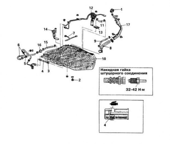
Fuel tank installation details for Mirage models 1990÷1992.
1 - Filler cap; 2 - Drain plug; 3 - Return hose; 4 - Fuel supply hose (pressure line); 5 - Check valve; 6 - Fuel vapor discharge hoses; 7 - Electrical wiring; 8 - Filler neck connecting hose; 9 - Ventilation hose; 10 - Fuel tank; 11 - Fuel vapor discharge hose; 12 - Fuel pump; 13 - Fuel intake mesh filter; 14 - Fuel consumption measurement unit; 15 - Fuel vapor discharge hose; 16 - Two-way valve; 17 - Filler neck
Warning! Remember that gasoline is highly flammable! When working with fuel system components, observe all accepted fire safety measures. Do not smoke! Do not approach the work area with an open flame or unprotected portable appliance! Do not service the system in rooms equipped with natural gas heating devices equipped with a pilot flame (such as water heaters and clothes dryers). Do not forget that gasoline is a carcinogen, i.e., a substance that promotes the development of cancer! Try to avoid fuel coming into contact with exposed areas of the body, use rubber protective gloves, and in case of accidental contact with fuel, wash your hands thoroughly with warm water and soap. Collect spilled fuel immediately and do not store rags soaked in fuel near open flames. Remember that the fuel system of models equipped with fuel injection is constantly under pressure. Before disconnecting fuel lines, relieve residual pressure in the system. Wear safety glasses when servicing fuel system components. Always keep a Class B fire extinguisher on hand!
Mirage models 1990÷1992.
Removal
1. The fuel pump/flow sensor assembly installation details on Mirage models produced in 1990-1992 are shown in the illustration.
2. Release the pressure in the fuel system (see Section Relieving pressure in the fuel system).
3. Disconnect the negative cable from the battery.
Warning! If the car stereo system is equipped with a security code, make sure you have the correct combination to activate the audio system before disconnecting the battery!
4. Drain any remaining fuel from the tank into a suitable receiving container.
5. Lower the fuel tank assembly slightly and disconnect the electrical wiring and communication lines connected to its top.
6. Remove the fuel tank from the vehicle (see Section Removal and installation the fuel tank).
7. Remove the five mounting nuts and remove the fuel pump/flow sensor assembly from the tank.
Installation
1. Install the fuel pump/flow sensor assembly in its original location - do not forget to replace the sealing gasket. Screw on and tighten the mounting nuts.
2. Install the fuel tank assembly to the vehicle (see Section Removal and installation the fuel tank).
3. Lower the vehicle to the ground and pour the drained fuel back into the gas tank.
4. Connect the negative cable to the battery.
5. Check the pressure characteristic of the fuel pump (see Section Checking the proper functioning of the fuel pump, measuring the fuel pressure). Inspect the fuel system path for signs of developing leaks.
Front-wheel drive (FWD) Galant models 1990÷1993.
Removal
1. Release the pressure in the fuel system (see Section Relieving pressure in the fuel system).
2. Disconnect the negative cable from the battery.
Warning! If the car stereo system is equipped with a security code, make sure you have the correct combination to activate the audio system before disconnecting the battery!
3. Drain any remaining fuel from the tank into a suitable receiving container.
4. Disconnect the electrical wiring connected to the fuel pump assembly, make sure that there is enough slack in the fuel flow sensor wiring harness to lower the tank. If necessary, also disconnect the sensor wiring, having previously marked the harness.
5. Disconnect the pressure line from the pump.
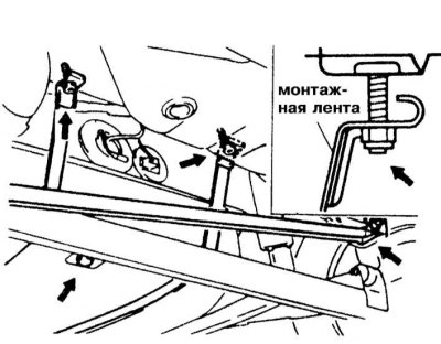
6. Loosen the self-locking nuts securing the tank mounting brackets
7. Remove the bolts securing the right crossbar and disconnect the lever from the body element joint. Lower the crossbar and tie it with wire to the rear axle assembly.
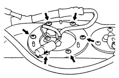
8. Remove the six mounting bolts and the sealing gasket installed in the base of the tank.
9. Remove the fuel pump assembly.
Installation
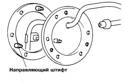
1. Align the three guide pins mounted on the gasket with the corresponding holes in the pump assembly. Make sure that the nipples are facing the same direction as before removing the pump.
2. Pass the mounting bolt through the hole in the bottom of the tank (remember to replace the sealing gasket) and tighten it to the required torque (14 N·m).
3. Install the right crossbar, screw the mounting bolt into the corresponding body joint and tighten it loosely.
4. Tighten the self-locking nuts of the tank mounting bands until it fits snugly on the vehicle. Tighten the nuts to the required torque (31 N·m).
5. Connect the pressure hose and tighten its nipple to the required torque (40 Nm).
6. Connect the electrical wiring to the fuel pump/flow sensor assembly.
7. Lower the vehicle to the ground and finally tighten the crossbar mounting bolt to the required torque (80÷100 Nm).
8. Pour the drained fuel back into the tank.
9. Connect the negative cable to the battery.
10. Check the proper functioning of the power supply system, inspect its tract for signs of developing leaks.
All-wheel drive models (AWD) Galant 1990÷1993.
Removal
1. Release the pressure in the fuel system (see Section Relieving pressure in the fuel system).
2. Disconnect the negative cable from the battery.
Warning! If the car stereo system is equipped with a security code, make sure you have the correct combination to activate the audio system before disconnecting the battery!
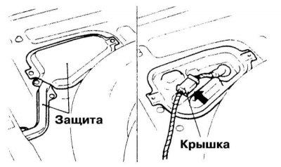
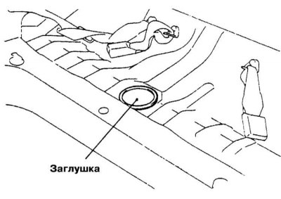
3. The fuel pump is located inside the tank. Remove the access cover installed in the rear floor panel of the vehicle.
4. Drain the remaining fuel from the tank into a suitable receiving container.
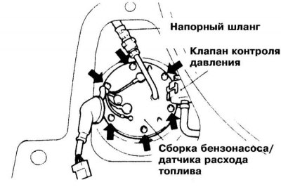
5. Disconnect the electrical wiring from the pump assembly.
6. If necessary, remove the two-way valve that controls the fuel level in the tank.
7. Disconnect the pressure line.
The source of the article is available at mitsubishiman.ru
8. Remove the six mounting bolts and remove the fuel pump/flow sensor assembly from the tank.
9. Align the three guide pins mounted on the gasket with the corresponding holes in the pump assembly. Make sure that the nipples are facing the same direction as before removing the pump. Install the holders and tighten them to the required torque (3 N·m).
10. Connect the pressure hose and tighten its nipple to the required torque (40 Nm).
11. Reinstall the two-way restrictor valve and connect the electrical wiring to the pump assembly.
12. Pour the drained fuel back into the tank.
13. Connect the negative cable to the battery.
14. Check the proper functioning of the power supply system, inspect its tract for signs of developing leaks.
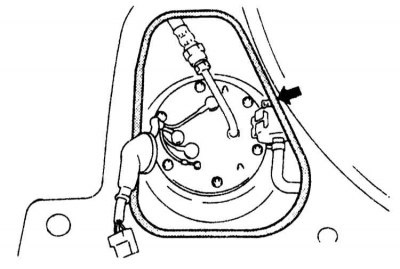
15. Place 3M ATD #8625 sealant on the floor panel, then install and secure the service cover.
Models Galant 1994-1998, Mirage 1993-2000 and Diamante
Removal
1. Release the pressure in the fuel system (see Section Relieving pressure in the fuel system).
2. Disconnect the negative cable from the battery.
Warning! If the car stereo system is equipped with a security code, make sure you have the correct combination to activate the audio system before disconnecting the battery!
3. Remove the rear seat cushion (see Chapter Body).
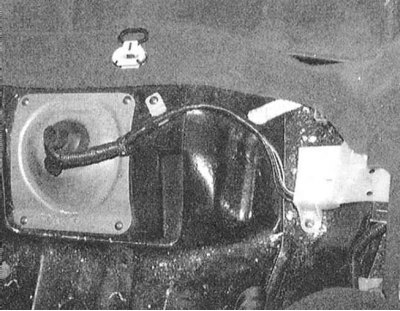
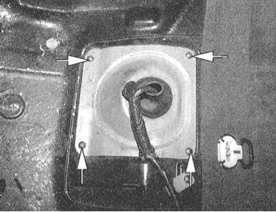
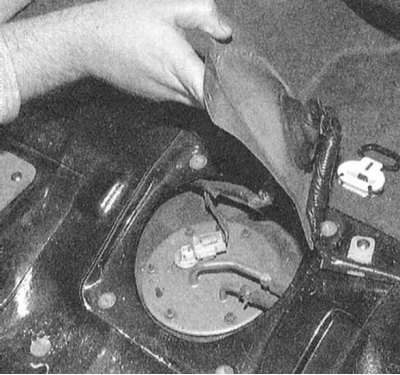
4. Remove the service access cover to the submersible fuel pump/fuel flow sensor assembly.
 |  |
 |  |
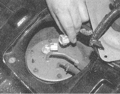 |  |
5. Disconnect the electrical wiring from the pump assembly.
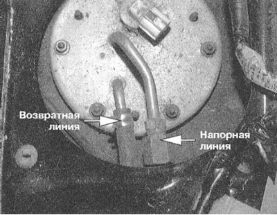
6. Disconnect the return hose and pressure line.
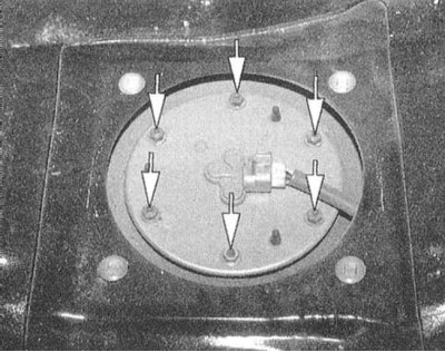
7. Remove the mounting nuts and remove the assembly.
Installation
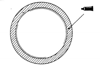
1. Place a new sealing gasket on the tank seating surface.
2. Fill the fuel pump/flow sensor assembly into the tank. Screw in the mounting bolts and tighten them to the required torque (2.5 N·m).
Note: When inserting the pump assembly into the tank, the fuel flow sensor measuring float should be bent to the left.
3. Connect the pressure line and fuel return hose to the assembly.
4. Connect the electrical wiring.
5. Connect the negative cable to the battery.
6. Check the pressure characteristic of the fuel pump (see Section Checking the proper functioning of the fuel pump, measuring the fuel pressure). Inspect the fuel system components for signs of developing leaks.
7. Seal the service cover to the pump with sealant. Install the rear seat cushion in place (see Chapter Body).
Galant models 1999 and 2000.
Removal
1. Release the pressure in the fuel system (see Section Relieving pressure in the fuel system).
2. Disconnect the negative cable from the battery.
Warning! If the car stereo system is equipped with a security code, make sure you have the correct combination to activate the audio system before disconnecting the battery!
3. Remove the rear seat cushion (see Chapter Body).
4. Remove the service access cover to the submersible fuel pump/fuel flow sensor assembly.
5. Disconnect the electrical wiring from the pump assembly.
6. Disconnect the return hose and pressure line.
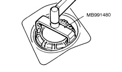
7. Using a special tool such as MB991480, release the retaining cap and remove the fuel pump/fuel flow sensor assembly.
Installation
1. Place a new sealing gasket on the tank seating surface.
2. Fill the fuel pump/fuel flow sensor assembly into the tank, - make sure that the mounting marks on the assembly and the floor panel are correctly aligned.
3. Using the special tool MB991480, tighten the retaining cap.
4. Connect the pressure line and fuel return hose to the assembly.
5. Connect the electrical wiring.
6. Connect the negative cable to the battery.
7. Check the pressure characteristic of the fuel pump (see Section Checking the proper functioning of the fuel pump, measuring the fuel pressure). Inspect the fuel system components for signs of developing leaks.
8. Place the pump access cover onto the sealant.
9. Reinstall the rear seat cushion (see Chapter Body).