
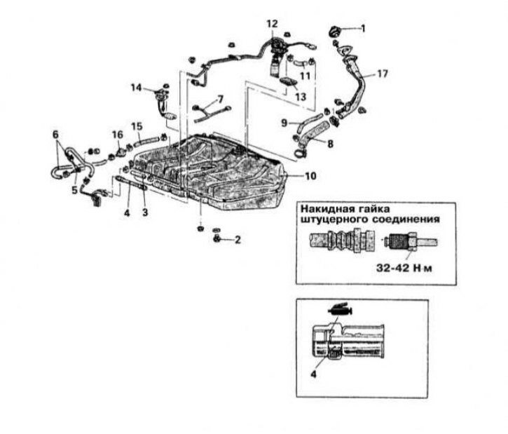
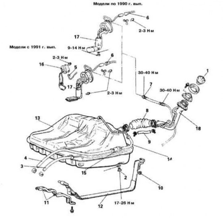
Details of fuel tank installation on Mirage models 1990÷1992. issue
1 - Filler cap; 2 - Drain plug; 3 - Return hose; 4 - Fuel supply hose (pressure line); 5 - Control valve; 6 - Hoses for removing fuel vapors; 7 - Wiring; 8 - Connecting hose of the filler neck; 9 - Ventilation hose; 10 - Fuel tank; 11 - Hose for removal of fuel vapors; 12 - Fuel pump; 13 - Mesh filter of the fuel intake; 14 - Block for measuring fuel consumption; 15 - Hose for removal of fuel vapors; 16 - Two-way valve; 17 - Filler neck
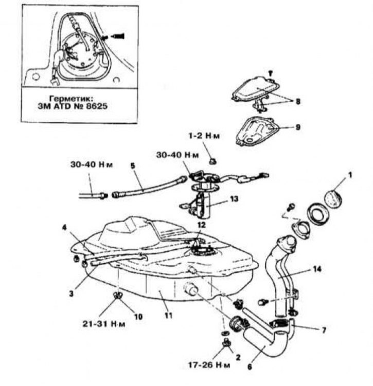
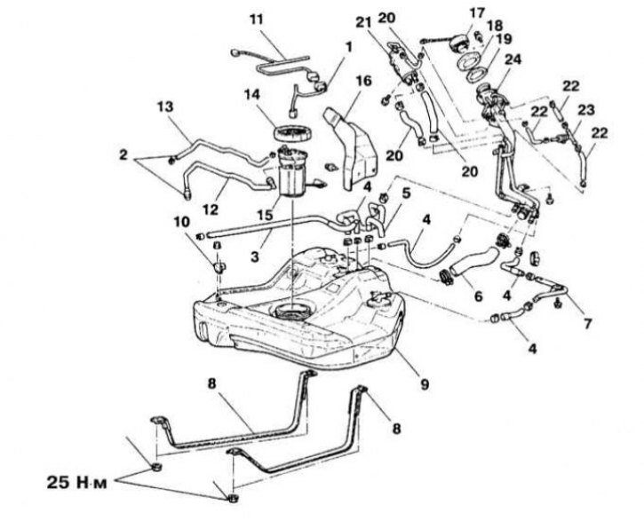
Details of fuel tank installation on Mirage models 1993÷1996. issue
1 - Filler neck; 2 - Hose for removal of fuel vapors; 3 - nipple connector of the pressure line; 4 - Union connector of the return hose; 5 - Hose for removal of fuel vapors; 6 - Contact connector for the electrical wiring of the fuel pump and fuel consumption sensor; 7 - Wiring of rear wheel speed sensors (models with ABS); 8 - Assembling the fuel tank; 9 - Block for measuring fuel consumption; 10 - Sealing gasket; 11 - Fuel supply hose (pressure line); 12 - Return hose; 13 - Fuel pump; 14 - Sealing gasket; 15 - Hose for removal of fuel vapors; 16 - Shut-off valve of the fuel path; 17 - Wiring of the fuel pump and fuel consumption sensor
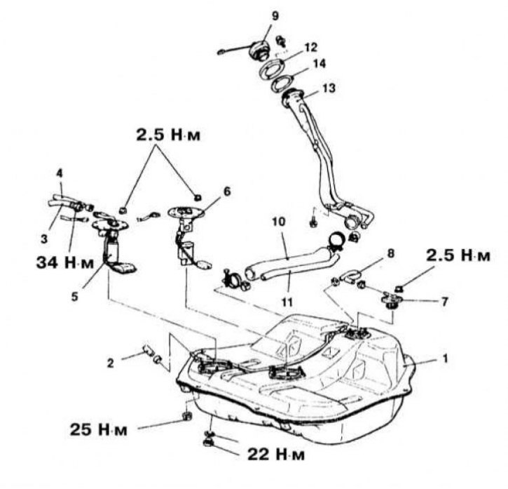
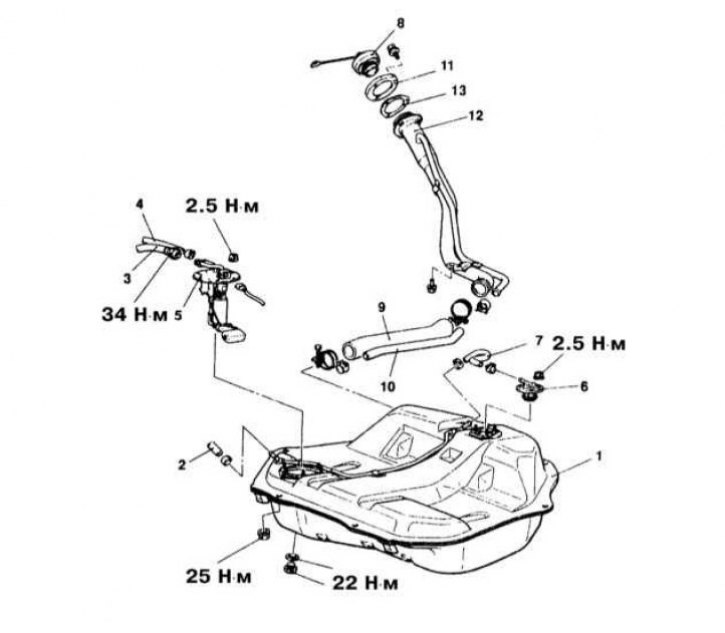
Fuel tank installation details on 1997 and 1998 Mirage models. issue
1 - Filler cap; 2 - Sealing gasket; 3 - Filler neck; 4 - Return hose; 5 - Pressure hose; 6 - Fitting; 7 - Contact connector for electrical wiring; 8 - Fuel tank; 9 - Connecting hose of the filler neck; 10 - Level hose; 11 - Hose for removal of fuel vapors; 12 - Fuel tank safety valve; 13 - Hose for removal of fuel vapors; 14 - Shut-off valve of the fuel path; 15 - Fuel pump; 16 - Fuel consumption measurement unit
Fuel tank installation details on 1999 and 2000 Mirage models. issue
1 - Shield of the filler neck; 2 - Shield of the filler neck; 3 - Filler cap; 4 - Sealing gasket; 5 - Hose for removal of fuel vapors; 6 - Separator; 7 - Hose for removal of fuel vapors; 8 - Assembly of the control valve; 9 - Filler neck; 10 - Return hose; 11 - Pressure line; 12 - Wiring; 13 - Hose for removal of fuel vapors; 14 - Connecting tube; 15 - Pipe for removal of fuel vapors; 16 - Shut-off valve of the fuel path; 17 - Connecting hose of the filler neck; 18 - Fuel cut-off valve; 19 - Level hose; 20 - Level valve; 21 - Fuel pump; 22 - Block for measuring fuel consumption; 23 - Fuel tank; 24 - Purge hose
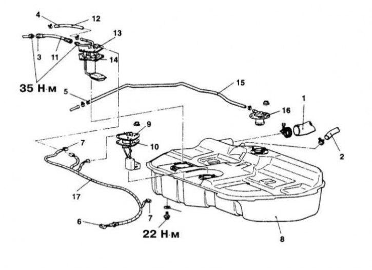
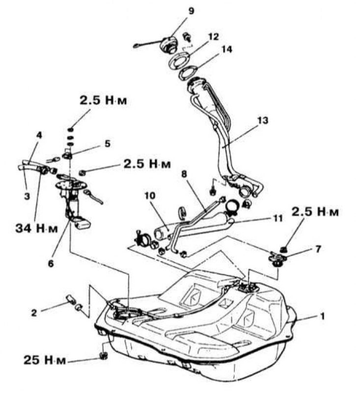
Details of fuel tank installation on Galant FWD models 1990÷1993. issue
1 - Filler cap; 2 - Drain plug; 3 - Return hose; 4 - Hose for removal of fuel vapors; 5 - Contact connector for the electrical wiring of the fuel consumption measurement unit; 6 - Contact connector for the electrical wiring of the fuel pump; 7 - nipple connector for connecting the pressure line to the fuel pump; 8 - Connecting hose of the filler neck; 9 - Hose for removal of fuel vapors; 10 - Self-locking nut; 11 - Mounting tape support bracket; 12 - Mounting tape; 13 - Fuel tank; 14 - Hose for removal of fuel vapors; 15 - Control valve of the fuel tank; 16 - Block for measuring fuel consumption; 17 - Fuel pump; 18 - Filler neck
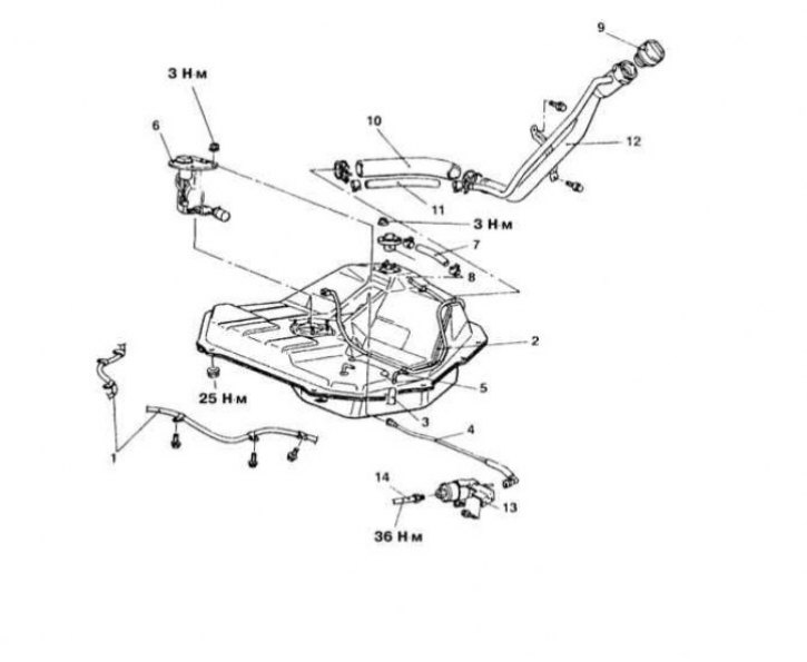
Fuel tank installation details on Galant AWD models 1990÷1993. issue
1 - Filler cap; 2 - Drain plug; 3 - Return hose; 4 - Hose for removal of fuel vapors; 5 - Pressure line; 6 - Connecting hose of the filler neck; 7 - Hose for removal of fuel vapors; 8 - Shield; 9 - Hollow cover; 10 - Self-locking nut; 11 - Fuel tank; 12 - Control valve; 14 - Filler neck
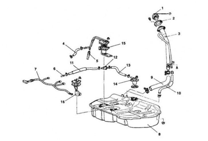
Details of fuel tank installation on Galant models 1994÷1996. issue (except California)
1 - Fuel tank; 2 - Hose for removal of fuel vapors; 3 - Pressure line; 4 - Return hose; 5 - Gasoline pump; 6 - Block for measuring fuel consumption; 7 - Shut-off valve; 8 - Hose for removal of fuel vapors; 9 - Filler cap; 10 - Connecting hose of the fuel filler; 11 - Hose for removal of fuel vapors; 12 - Holder; 13 - Filler neck; 14 - Sealing gasket
Details of the installation of the fuel tank on the California models Galant 1994÷1996. issue
1 - Fuel tank; 2 - Hose for removal of fuel vapors; 3 - Pressure line; 4 - Return hose; 5 - Assembly of the fuel pump and fuel consumption meter unit; 6 - Shut-off valve; 7 - Hose for removal of fuel vapors; 8 - Filler cap; 9 - Connecting hose of the filler neck; 10 - Hose for removal of fuel vapors; 11 - Holder; 12 - Filler neck; 13 - Sealing gasket
Fuel tank installation details on 1997 and 1998 Galant models. issue
1 - Fuel tank; 2 - Hose for removal of fuel vapors; 3 - Pressure line; 4 - Return hose; 5 - Differential fuel tank pressure sensor; 6 - Assembly of the fuel pump and fuel consumption meter unit; 7 - Shut-off valve; 8 - Hose for removal of fuel vapors; 9 - Filler cap; 10 - Connecting hose of the filler neck; 11 - Hose for removal of fuel vapors; 12 - Holder; 13 - Filler neck; 14 - Sealing gasket
Fuel tank installation details on 1999 and 2000 Galant models. issue
1 - Wiring; 2 - Union connectors; 3 - Purge hose; 4 - Hose for removal of fuel vapors; 5 - Ventilation hose; 6 - Connecting hose of the filler neck; 7 - Tube; 8 - Mounting tapes; 9 - Fuel tank; 10 - Differential pressure sensor; 11 - Wiring; 12 - Pressure line; 13 - Return hose; 14 - Cover; 15 - Assembly of the fuel pump; 16 - Shield; 17 - Filler cap; 18 - Amplifier; 19 - Sealing gasket; 20 - Hose for removal of fuel vapors; 21 - Separator; 22 - Hose for removal of fuel vapors; 23 - Control valve; 24 - Filler neck
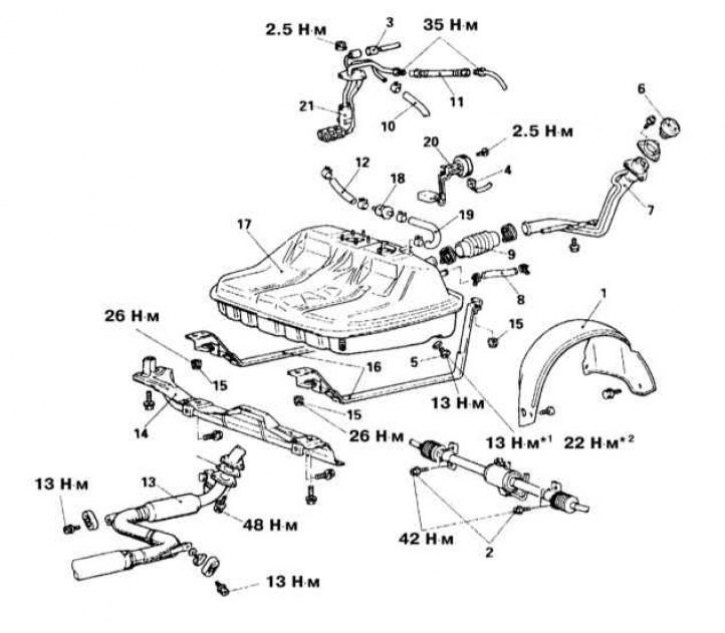
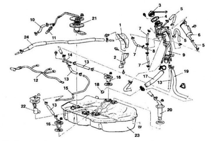
Details of fuel tank installation on Diamante models 1992÷1996. issue
1 - Wheel arch protection locker (DOHC); 2 - Booster cylinder mounting bolts (models with 4WS); 3 - Electrical wiring of the fuel pump; 4 - Electrical wiring of the fuel consumption meter; 5 - Drain plug; 6 - Filler cap; 7 - Filler neck; 8 - Hose for removal of fuel vapors; 9 - Connecting hose of the filler neck; 10 - Return hose; 11 - Pressure line; 12 - Hose for removal of fuel vapors; 13 - Central section of the exhaust system; 14 - Fuel tank protection; 15 - Self-locking nut; 16 - Mounting tape; 17 - Fuel tank; 18 - Safety valve; 19 - Hose for removal of fuel vapors; 20 - Block for measuring fuel consumption; 21 - Fuel pump
Details of fuel tank installation on Diamante models 1997÷2000. issue
1 - Parking brake cable; 2 - Fuel tank; 3 - Hose for removal of fuel vapors; 4 - Pressure line; 5 - Hose for removal of fuel vapors; 6 - Assembly of the fuel pump and fuel consumption measurement unit; 7 - Hose for removal of fuel vapors; 8 - Valve assembly; 9 - Filler cap; 10 - Connecting hose of the filler neck; 11 - Hose for removal of fuel vapors; 12 - Filler neck; 13 - Fuel filter; 14 - Fuel line
Warning! Remember that gasoline is a highly flammable liquid! Observe all applicable fire safety precautions when working on power system components. Do not smoke! Do not approach the place of work with an open flame or carrying an unprotected lampshade! Do not service the system in rooms equipped with natural gas-fired heaters equipped with a pilot flame (such as water heaters and clothes dryers). Do not forget that gasoline is classified as a carcinogen, i.e., substances that contribute to the development of cancer! Try to avoid getting fuel on open areas of the body, use rubber protective gloves, in case of accidental unexpected contact with fuel, thoroughly wash your hands with warm water and soap. Clean up spilled fuel immediately and do not store fuel-soaked rags near open flames. Remember that the fuel injection system of models equipped with fuel injection is constantly under pressure. Relieve any residual pressure in the system before attempting to disconnect fuel lines. Wear safety goggles when servicing power system components. Keep a class B fire extinguisher handy at all times!
Removing
1. Details of the installation of the fuel tank are shown in the illustrations.
2. Relieve pressure in the supply system (see Section Depressurizing the supply system).
3. Disconnect the negative cable from the battery.
Attention! If the stereo system installed in the car is equipped with a security code, before disconnecting the battery, make sure that you have the correct combination to activate the audio system!
4. Jack up the car and put it on stands.
5. Drain the remaining fuel from the gas tank into a suitable receiving container.
6. On Diamante models:
- a) Remove the left rear wheel arch protection locker;
- b) Disconnect the center section of the exhaust system from the main muffler. Remove the rear section of the exhaust system from the suspensions and lower it, take it to the side and tie it up;
- c) On models equipped with rear wheel steering, remove the mounting bolts and remove the rear steering assembly.
7. Disconnect the pressure and return hoses from the fuel pump assembly. Also disconnect the fuel evaporator hoses.
8. Disconnect the wiring harness from the fuel pump/fuel flow measurement unit assembly.
9. Disconnect the filler neck and ventilation hoses from the tank.
10. Get a suitable jack under the center of the tank, support the assembly with it and give the mounting bracket nuts (tapes).
11. Slightly lower the tank and disconnect the remaining communication lines from it (electrical wiring, hoses, pipes, etc.).
12. Remove the tank from under the car.
Installation
1. If the tank is to be replaced, transfer various attachments from the tank to the replacement assembly, including heat shields, connecting hoses, valves, and the fuel pump/fuel flow sensor assembly.
2. Attach the new tank to the head of the jack and slide it into place under the bottom of the car - leave enough clearance to connect the communication lines to the top of the pump assembly.
3. Connect the appropriate communication lines to the top of the tank.
4. Cock up the jack, finally bringing the tank to its regular position. Install mounting straps and secure with new self-locking nuts.
5. Restore the original connection of the pressure and return lines.
6. Connect the filler hose and vent line. Secure the filler neck assembly to the fender of the car with special screws.
7. On Diamante models:
- a) With the appropriate configuration, install the power steering of the rear wheels, screw in the fixing bolts and tighten them with the required force (43 Nm);
- b) Install and secure the rear section of the exhaust system on the hangers;
- c) If removed, install the left rear wheel arch locker.
8. Lower the vehicle to the ground and pour the drained fuel back into the tank. Check the operation of the fuel pump (see below), inspect the power system path for signs of leak development.