



Contents: Removal and installation of fuel…⤓ Removal and installation injectors ⤓ Removal and installation the…⤓ Removal and installation the…⤓ Removal and installation the…⤓
Removal and installation of fuel injection pump
− Before you begin removing parts, perform the following operations:
- a) Remove the engine cover.
- b) Release residual pressure from the high-pressure fuel line,
- c) Remove the air filter.
- d) Remove the throttle body.
Removal is carried out in the order of the numbers indicated in the figure "Removing the fuel injection pump".
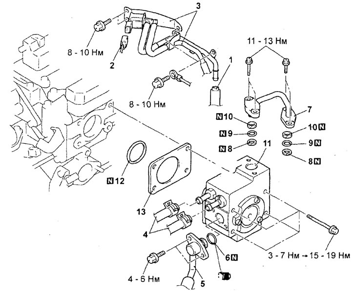
Removal the fuel injection pump (engine 4G15). 1 - connection of the vacuum hose of the adsorber; 2 - connector of the electromagnetic valve of the adsorber purge; 3 - bracket of the electromagnetic valve of the adsorber purge and vacuum tubes and hoses in assembly; 4 - fuel return hose connection; 5 - connection of the fuel inlet hose; 6 - O-ring gasket; 7 - high pressure fuel pipe (fuel supply); 8 - support washer "A"; 9 - O-ring gasket; 10 - support washer "B"; 11 - Fuel injection pump; 12 - O-ring gasket; 13 - insulator.
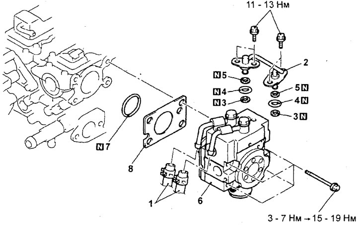
Removal the fuel injection pump (engine 4G93). 1 - fuel return hose connection; 2 - high pressure fuel pipe (fuel supply); 3 - support washer "A"; 4 - O-ring gasket; 5 - support washer "B"; 6 - Fuel injection pump; 7 - O-ring gasket; 8 - insulator.
Installation is carried out in the reverse order of removal.
When installing parts, please pay attention to the following operations:
1. Installing the high-pressure fuel pump, high-pressure fuel pipe (fuel supply), support washer "A", ring gasket and support washer "B".
a) Apply a small amount of clean engine oil to the outer O-ring of the injection pump protrusion and the injection pump drive roller.
Caution: Do not allow engine oil to enter the injection pump.
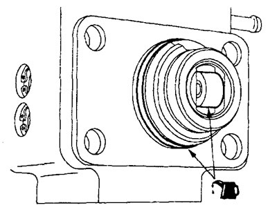
Engine 4G15.
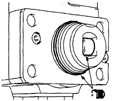
Engine 4G93.
b) Insert the protruding part of the high-pressure fuel pump evenly into the corresponding hole in the cylinder head. Make sure that the protruding part of the high-pressure fuel pump is inserted securely, evenly, without distortions, then pre-tighten the high-pressure fuel pump mounting bolts with a small torque (slightly more than hand tightening).
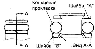
c) Install the support washer "B", O-ring and support washer "A" onto the high pressure fuel pipe as shown in the figure.
Attention:
- Install the thrust washer "B" with the beveled surface facing away from the O-ring.
- Make sure that the support washer "A" (outer diameter 14.8 mm) is installed correctly. Do not confuse the support washer "A" with the support washer of the fuel pressure sensor.
d) Apply a small amount of clean engine oil to the O-ring of the high pressure fuel pipe.
Caution: Do not allow engine oil to enter the injection pump or fuel manifold.
d) Insert the high-pressure fuel pipe straight into the injection pump and into the fuel manifold. Make sure that the fuel pipe is inserted securely, straight, and without distortion, then tighten the fuel pipe mounting bolts to the rated torque.
Tightening torque: 11 - 13 Nm
e) Tighten the fuel injection pump mounting bolts to a torque of 5 + 2 Nm in the order shown in the figure.
Note: When tightening, use a torque wrench with a scale step of 0.5 N·m.
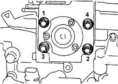
Engine 4G15.
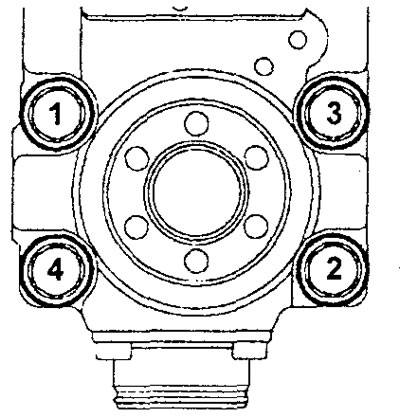
Engine 4G93.
g) Finally tighten the fuel injection pump mounting bolts to a torque of 17±2 Nm.
2. Installing the O-ring and fuel inlet hose.
a) Apply a small amount of clean engine oil to the O-ring of the fuel inlet hose.
Caution: Do not allow engine oil to enter the injection pump.
b) Be careful not to damage the O-ring when installing. Connect the fuel hose flange to the high-pressure fuel pump by turning it from side to side. After connecting, check that the flange rotates freely without jamming.
c) If the fuel hose flange does not rotate smoothly, the O-ring may be pinched. In this case, disconnect the fuel hose, check the condition of the O-ring, and replace it if necessary. Reconnect the fuel hose and check the flange for smooth rotation again.
d) Tighten the hose mounting bolts to the specified torque.
Tightening torque: 5±1 Nm
3.Installing the fuel return hose.
Install the fuel return hose so that the identification mark is directed as shown in the illustration.
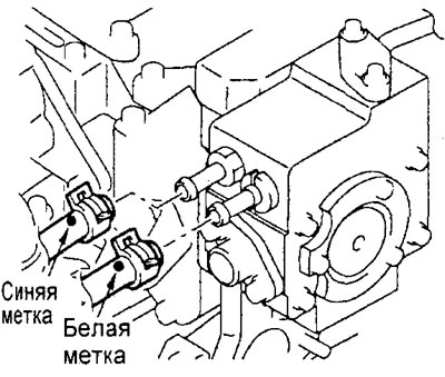
Engine 4G15.
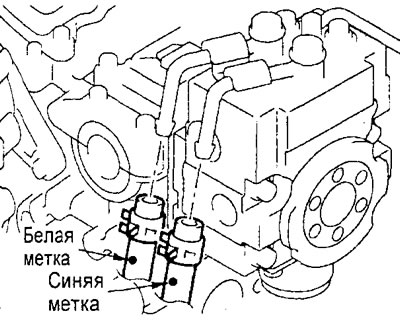
Engine 4G93.
4. Removing air from the high pressure fuel supply.
a) Start the engine and let it run at 2000 rpm for 15 seconds or more to remove air from the injection pump.
b) If diagnostic trouble code P0190 (incorrect fuel pressure) is detected, clear it using a tester.
Note: DTC P0190 will set if the fuel line has been removed and air has entered the high pressure fuel line or injection pump.
After completing the installation of the parts, perform the following operations:
- a) Install the throttle body.
- 6) Install the air filter.
- c) Perform the procedure for bleeding air from the high-pressure fuel line.
- d) Check for fuel leaks.
- e) Install the engine casing.
Removal and installation injectors
Before you begin removing parts, remember the following:
- a) Remove the engine cover.
- b) Release residual pressure from the high-pressure fuel line.
- c) Disconnect the cable from the negative terminal of the battery.
- d) (Engine 4G15) Remove the air filter.
- d) (Engine 4G15) Remove the throttle body.
- e) (Engine 4G15) Remove the intake manifold.
The parts are removed in the order of the numbers indicated in the figure "Removing the injectors".
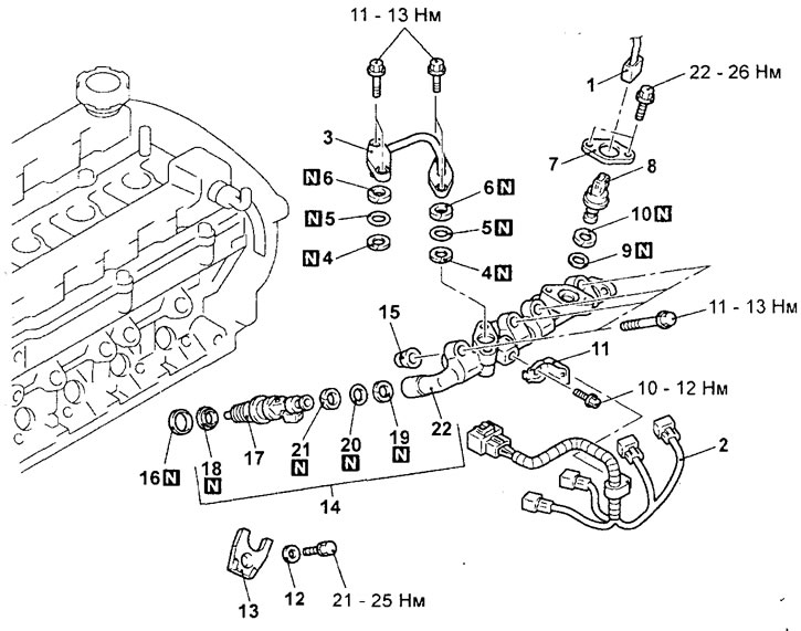
Removal injectors (engine 4G15). 1 - fuel pressure sensor connector; 2 - connector of injector wiring harness; 3 - high pressure fuel pipe (fuel supply); 4 - support washer "A"; 5 - O-ring gasket; 6 - support washer "B"; 7 - flange; 8 - fuel pressure sensor; 9 - O-ring gasket; 10 - support washer; 11 - injector wiring harness retainer bracket; 12 - washer; 13 - nozzle holder; 14 - fuel manifold assembly; 15 - insulator; 16 - gasket; 17 - nozzle; 18 - figured washer; 19 - support washer "A"; 20 - O-ring gasket; 21 - support washer "B"; 22 - fuel manifold.
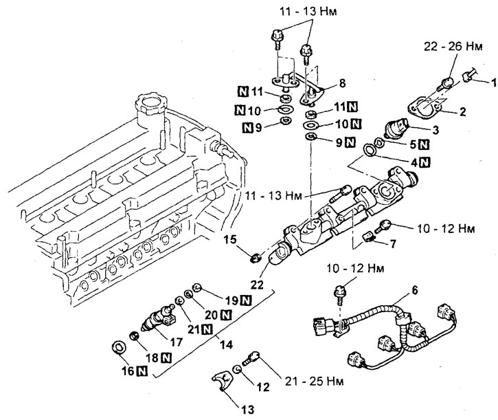
Removal injectors (engine 4G93). 1 - fuel pressure sensor connector; 2 - flange; 3 - fuel pressure sensor; 4 - O-ring gasket; 5 - support washer (remove the air filter; throttle body and intake manifold); 6 - injector wiring harness connector; 7 - bracket for injector wiring harness retainer; 8 - high pressure fuel pipe (fuel supply); 9 - support washer "A"; 10 - O-ring gasket; 11 - support washer "B"; 12 - washer; 13 - nozzle holder; 14 - fuel manifold assembly; 15 - insulator; 16 - gasket; 17 - nozzle; 18 - figured washer; 19 - support washer "A"; 20 - O-ring; 21 - support washer "B"; 22 - fuel manifold.
When removing parts, pay attention to the following operations:
1. Removing the flange.
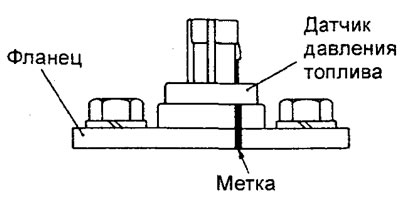
If the fuel pressure sensor is to be reused, make alignment marks on the flange and on the sensor before removing the flange.
Note: When tightening the fastening to the engine, the flange is deformed. Therefore, to ensure reliable sealing of the fuel pressure sensor and its correct installation, it is necessary to apply marks as shown in the figure to reinstall the sensor in its original position. When replacing the fuel pressure sensor, it is replaced only together with the flange.
2. Removing the fuel manifold. Remove the fuel manifold assembly with the injectors.
Caution: Be careful not to drop the injectors when removing the fuel rail.
Installation is carried out in the reverse order of removal.
When installing parts, please pay attention to the following operations:
1. Installing the support washer "B", the ring gasket, the support washer "A" and the injector shaped washer.
a) Install the washers and O-ring as shown in the figure.
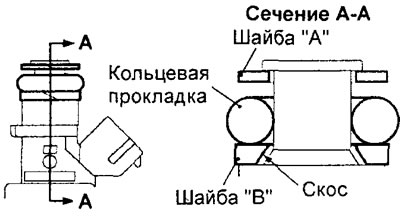
Attention:
- Install the thrust washer "B" with the beveled surface facing away from the O-ring.
- Make sure that the support washer "A" (outer diameter 14.8 mm) is installed correctly. Do not confuse the support washer "A" with the support washer of the fuel pressure sensor.
6) Before installing a new shaped washer, apply white Vaseline to it. Be careful to make sure that the shaped washer is installed correctly (see the picture).
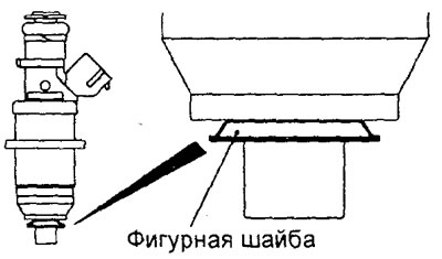
Caution: The shaped washer must always be replaced during disassembly and assembly work, as reusing the washer may cause fuel leakage or gas breakthrough.
2. Installing the fuel manifold assembly with injectors.
a) Apply a small amount of clean engine oil to the O-ring.
Caution: Be careful not to allow engine oil to enter the fuel rail.
b) When installing, do not damage the O-ring. Rotate the nozzle from side to side, install it into the fuel manifold. After connecting, make sure that the nozzle rotates freely.
c) If the injector turns with sticking, then most likely the O-ring has become jammed. In this case, remove the injector, check the condition of the seal and, if necessary, replace it, and then reinstall the injector.
d) Align the timing marks on the fuel manifold and injectors.
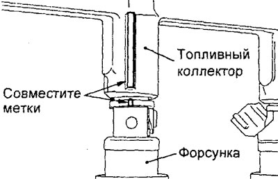
Engine 4G15.
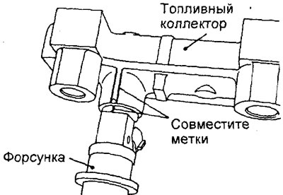
Engine 4G93.
d) Install gaskets on the cylinder head opening under the injectors and insulators. To prevent the insulators from falling, apply Vaseline to them.
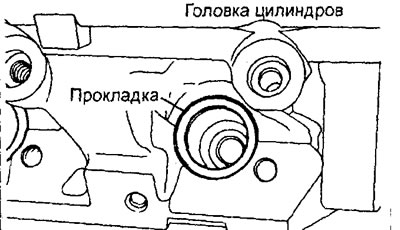
e) Install the fuel manifold together with the injectors on the cylinder head and pre-tighten the mounting bolts.
g) Install the injector holders with washers and tighten their mounting bolts to the specified torque.
Tightening torque: 21 - 25 Nm
h) Tighten the fuel rail mounting bolts to the specified torque in the order shown in the figure.
Tightening torque: 11 - 13 Nm
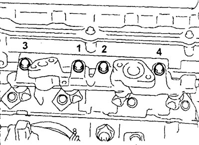
Engine 4G15.
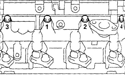
Engine 4G93.
3. Installing the thrust washer and O-ring.
Install the thrust washer and O-ring as shown in the illustration.
Caution: Do not confuse the support washer with the support washer "A" installed on the injector and high-pressure fuel pipe (fuel supply) (outer diameter 15.1 mm).
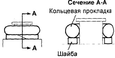
4. Installing the fuel pressure sensor and flange.
a) Apply a small amount of clean engine oil to the O-ring.
Caution: Do not allow engine oil to enter the fuel rail.
b) Install the fuel pressure sensor in the position as shown in the figure. If the fuel pressure sensor is reused, align the alignment marks on the flange and on the sensor.
Caution: When replacing the fuel pressure sensor, always replace it with a flange.
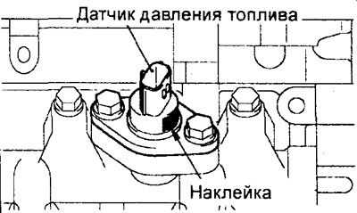
5. Installing the thrust washer "B", O-ring, thrust washer "A" and high-pressure fuel pipe (fuel supply).
a) Install the support washer "B", O-ring and support washer "A" to the high pressure fuel pipe as shown in the figure.
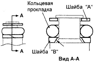
Attention:
- Install the thrust washer "B" with the beveled surface facing away from the O-ring.
- Make sure that the support washer "A" (outer diameter 14.8 mm) is installed correctly. Do not confuse the support washer "A" with the support washer of the fuel pressure sensor.
b) Apply a small amount of clean engine oil to the O-ring of the high pressure fuel pipe.
Caution: Do not allow fuel oil to enter the injection pump or fuel rail.
c) Insert the high-pressure fuel pipe straight into the injection pump and into the fuel manifold. Make sure that the fuel pipe is inserted securely, straight, and without distortions, then tighten the fuel pipe mounting bolts to the rated torque.
Tightening torque: 11 - 13 Nm
After completing the installation of the parts, perform the following operations:
- a) (Engine 4G15) Install the intake manifold.
- b) (Engine 4G15) Install the throttle body.
- c) (Engine 4G15) Install the air filter.
- d) Connect the wire to the negative terminal of the battery.
- d) Perform the procedure for removing air from the high-pressure fuel line (see paragraph "4" of the subsection "Removing and installing the high-pressure fuel pump").
- e) Check for fuel leaks.
- g) Install the engine cover.
Removal and installation the throttle body
Before you begin removing parts, perform the following operations:
- a) Remove the engine cover.
- b) Drain the coolant.
- c) Remove the air filter.
The parts are removed in the order of the numbers indicated in the figure "Removing the throttle body".
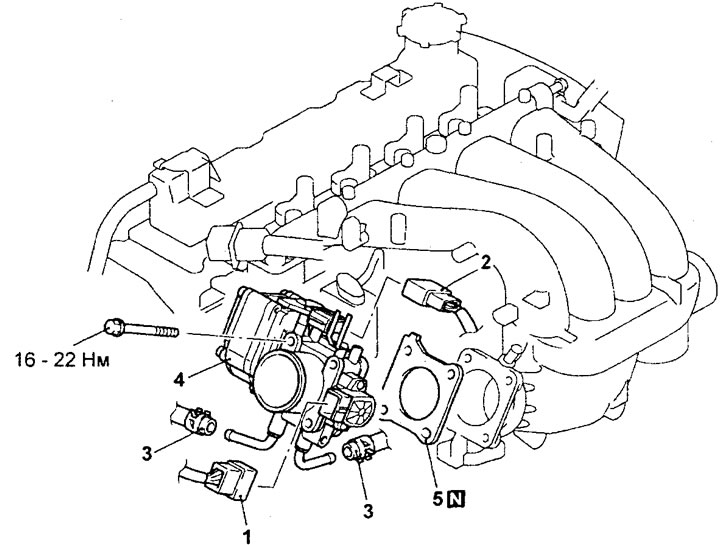
Removal the throttle body (engine 4G15). 1 - connector of the throttle position sensor, 2 - connector of the throttle servo, 3 - cooling system hose connection, 4 - throttle body assembly, 5 - throttle body gasket.
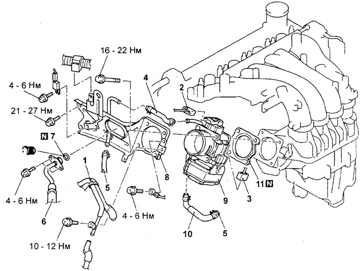
Removal the throttle body (engine 4G93). 1 - vacuum tubes and hoses assembly; 2 - throttle position sensor connector; 3 - throttle servo connector; 4 - Cooling system hose connection; 5 - Cooling system hose connection; 6 - connection of the fuel inlet hose; 7 - O-ring gasket; 8 - throttle body bracket; 9 - throttle body assembly; 10 - cooling system hose; 11 - throttle body gasket.
Installation is carried out in the reverse order of removal.
When installing parts, please pay attention to the following operations:
Caution: If the throttle position sensor is removed, it must be adjusted.
1. Installing the throttle body gasket.
Install the housing gasket so that its protrusion is positioned as shown in the figure.
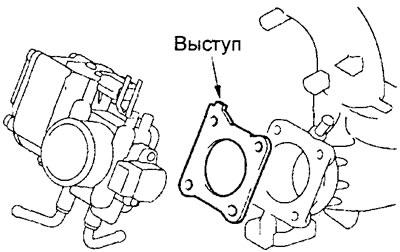
Engine 4G15.
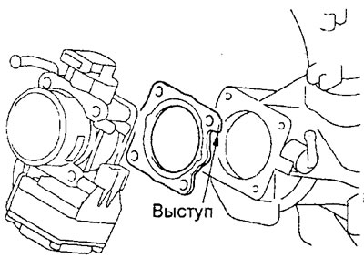
Engine 4G93.
2. (Engine 4G93) Installing the O-ring and fuel inlet hose.
a) Apply a small amount of clean engine oil to the O-ring of the fuel inlet hose.
Caution: Do not allow engine oil to enter the injection pump.
b) Be careful not to damage the O-ring when installing. Connect the fuel hose flange to the high-pressure fuel pump by turning it from side to side. After connecting, check that the flange rotates freely without jamming.
c) If the fuel hose flange does not rotate smoothly, the O-ring may be pinched. In this case, disconnect the fuel hose, check the condition of the gasket, and replace it if necessary. Reconnect the fuel hose and check the flange for smooth rotation again.
d) Tighten the hose mounting bolts to the specified torque.
Tightening torque: 4 - 6 Nm
3. Initializing the throttle control system after installing the throttle body.
Note: The throttle control system can only be initialized if the throttle body assembly is replaced.
a) Turn the ignition switch to the "ON" position, then within one second turn the ignition switch to the "LOCK" ("OFF") position.
b) Leave the ignition key in the "LOCK"("OFF") position for at least 10 seconds.
After completing the installation of the parts, perform the following operations:
- a) Install the air filter,
- b) Fill with coolant,
- c) Install the engine cover.
[The material is based on data from the website MitsubishiMan.ru]
Removal and installation the throttle servo controller
Before you begin removing parts, perform the following operations:
- a) Remove the glove box.
- b) Remove the front side door sill trim and front side trim.
The parts are removed in the order of the numbers shown in the figure "Removing the throttle servo controller".
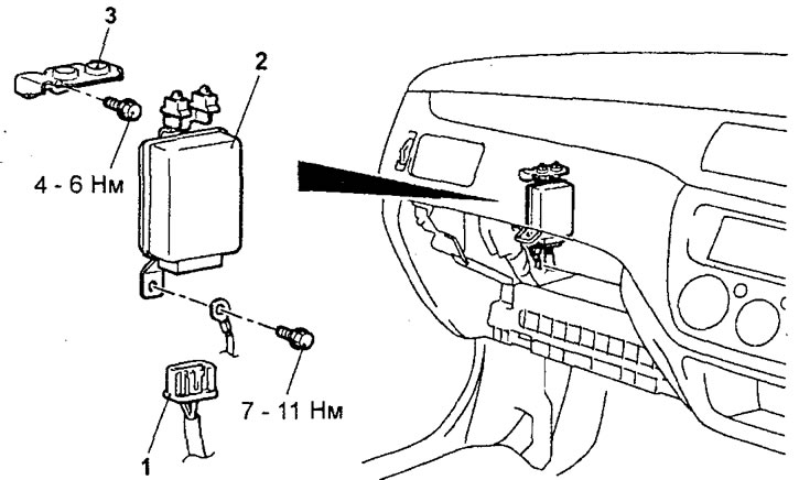
Removal the throttle servo controller. 1 - controller connector, 2 - throttle servo controller, 3 - bracket.
Installation is carried out in the reverse order of removal.
After completing the installation of the parts, perform the following operations:
- a) Install the front side trim and front side door sill trim.
- b) Install the glove box.
- If the throttle servo controller has been replaced, the throttle control system initialization procedure must be performed.
- a) Turn the ignition switch to the "ON" position, then within one second turn the ignition switch to the "LOCK" ("OFF") position.
- b) Leave the ignition key in the "LOCK" ("OFF") position for at least 10 seconds.
Removal and installation the injector control signal generator
The parts are removed in the order of the numbers indicated in the figure "Removing the injector control signal generator".
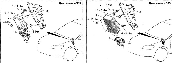
Removal the injector control signal generator. 1 - connector for the injector control signal generator, 2 - injector control signal generator, 3 - mounting bracket.
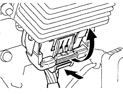
(Engine 4G93) When removing parts, pay attention to the operation of removing the injector control signal generator.
Press the connector at the location shown by the arrow in the figure to disconnect the connector.
Attention:
- Before disconnecting the connector of the injector control signal generator, it is necessary to disconnect the wire from the negative terminal of the battery.
- The injector signal generator housing becomes very hot during engine operation, so be careful when removing it.
Installation is carried out in the reverse order of removal.