
Note: the procedures for checking the EGR servomotor and the canister purge solenoid valve are given in the corresponding section of the chapter "Emission control system".
Location of system components
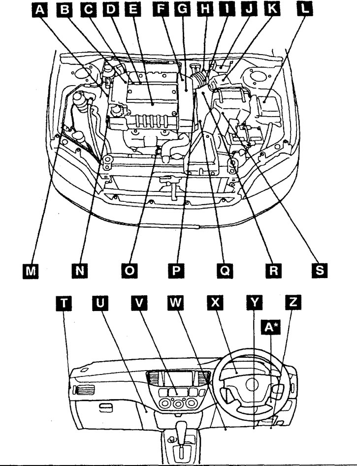
The location of the components of the fuel injection system. A - crankshaft position sensor, B - fuel pressure sensor, C - knock sensor, D - nozzle, E - ignition coil (with integrated power transistor), F - canister purge solenoid valve, G - EGR valve servomotor, H - throttle position sensor (channels #1 and #2), I - throttle servo, J - injector control signal generator, K - mass air flow sensor (with integrated intake air temperature sensor and atmospheric pressure sensor), L - main injection system relay, injector control relay and throttle servo relay, M - refrigerant pressure sensor, N - fluid pressure switch in the power steering hydraulic system, O - oxygen sensor, P - coolant temperature sensor, Q - camshaft position sensor, R - start inhibit switch, S - variator driven pulley speed sensor, T - throttle servo controller, U - engine and variator electronic control unit, V - air conditioning switch, W - diagnostic connector, X - indicator "CHECK ENGINE" (check the engine), Y - electronic control unit for electrical equipment, Z - accelerator pedal position sensor (channels #1 and #2), A* - fuel pump relay (#1 and #2) in the tank.
1. The location of the components may differ depending on the type of engine, year of manufacture and vehicle modification. However, the location of the main components of the fuel injection system (sensors and actuators of the engine management system), as a rule, is the same on engines of the same series.
2. Part of the components of the fuel injection systemlocated at the gearbox or in the exhaust system may be missing in the figures.
Main Injection Relay, Injector Control Relay and Throttle Servo Relay
1. Check for continuity between terminals "2" And "3" relay connector when power is off.
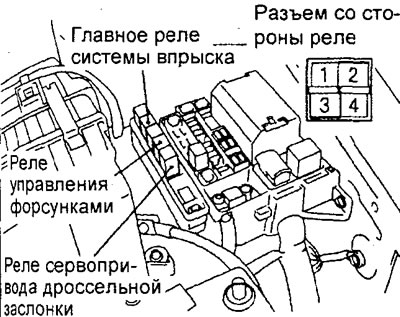
2. Connect the negative battery cable to the terminal "2" relay, and the positive terminal wire to the output "3" relay and check that the circuit is closed between the terminals "1"-"4" relay when battery powered.
Fuel pump relay
1. Check for continuity between terminals "1" And "4" relay connector when power is off.
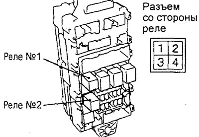
2. Connect the negative battery cable to the terminal "1" relay, and the positive terminal wire to the output "4" relay and check that the circuit is closed between the terminals "2"-"3" relay when battery powered.
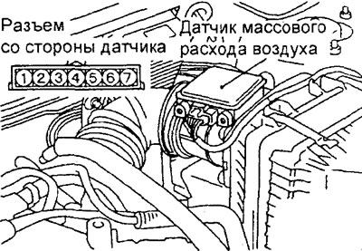
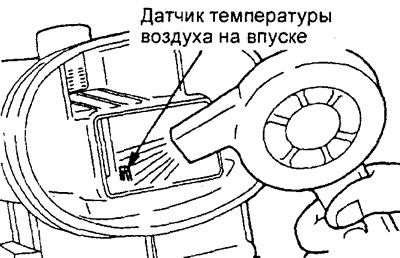
Intake air temperature sensor
1. Disconnect the mass air flow sensor connector.
2. Measure the resistance between the terminals of the connector "5" And "6".
Rated resistance:
- at 20°C - 2.3-3.0 kOhm
- at 80°C - 0.30-0.42 kOhm
3. Measure the resistance by heating the sensor with a hair dryer. As the temperature rises, the resistance should decrease.
4. If resistance does not correspond to nominal or does not change replace the gauge of the mass expense of air.
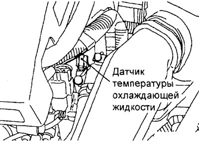
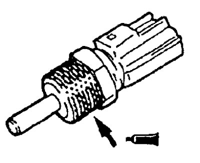
Coolant temperature sensor
1. Remove the coolant temperature sensor.
Engine 4G15.
Engine 4G93.
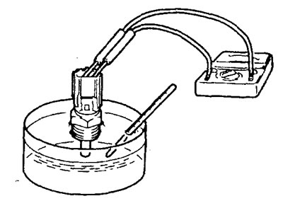
2. Measure the resistance between the sensor leads by immersing its sensing element in hot water.
Rated resistance:
- at 20°С - 2.10-2.70 kOhm
- at 80°C - 0.26-0.36 kOhm
3. If the measured resistance differs significantly from the nominal value, then replace the coolant temperature sensor.
4. Reinstall the coolant temperature sensor by applying sealant to the threads of the sensor.
Sealant - 3M NUT Locking Part #4171 or equivalent
5. Tighten the sensor to the specified nominal torque.
Tightening torque - 29 Nm
Throttle position sensor
1. Disconnect the throttle position sensor connector.
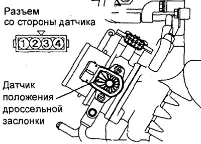
Engine 4G15.
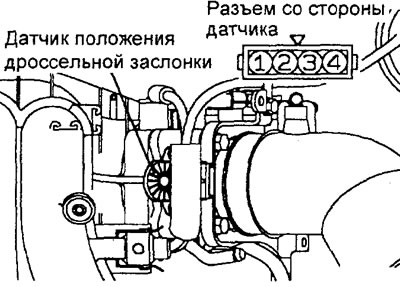
Engine 4G93.
2. Measure the resistance between the leads "weight" And "nutrition" sensor connector - pins "3" And "1".
Rated resistance - 1.7 - 3.3 kOhm
3. Measure the resistance between the leads "1"-"2" And "1"-"4" sensor connector by slowly opening the throttle from the fully closed position (idling) to the fully open position. The resistance should change smoothly in proportion to the throttle opening angle.
4. If the resistance differs from the nominal value, or does not change smoothly, then replace the throttle position sensor.
Note: after replacing the throttle position sensor, it must be adjusted.
5. Plug in the sensor connector.
Accelerator pedal position sensor
1. Disconnect the sensor connector.
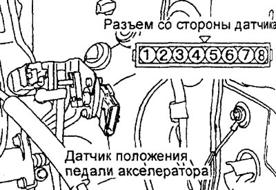
2. Measure the resistance between the indicated terminals ("weight" And "nutrition") sensor connector.
Conclusions:
- (channel #1) — "1"And "2"
- (channel #2) — "7" And "8"
Rated resistance - 3.5 - 6.5 kOhm
3. Measure the resistance between the indicated terminals ("nutrition" And "signal") sensor connector while slowly depressing the accelerator pedal. The resistance should change smoothly in proportion to the degree of pressure on the pedal.
Conclusions:
- (channel #1) — "2" And "3"
- (channel #2) — "8" And "6"
4. If the resistance differs from the nominal value, or does not change smoothly, then replace the accelerator pedal position sensor.
Note: after replacing the accelerator pedal position sensor, it must be adjusted.
5. Plug in the sensor connector.
The sensor - the switch of the released pedal of an accelerator
1. Disconnect the accelerator pedal position sensor connector.
2. Check the condition of the circuit between the terminals "4" And "5" ("sensor-switch" And "weight") at different positions of the accelerator pedal.
Rated value:
- Pedal pressed - circuit open
- Pedal released - circuit closed
3. In case of malfunction, replace the accelerator pedal position sensor.
Note: after replacing the accelerator pedal position sensor, it must be adjusted.
4. Plug in the sensor connector.
Oxygen sensor
1. Disconnect the oxygen sensor connector and connect the test harness to the connector on the sensor side.
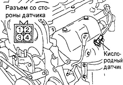
2. Measure the resistance between the leads "1" And "3" oxygen sensor connector (conclusions "+" and heating element).
Rated resistance (at 20°C) — 11-18 Ohm
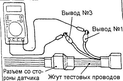
3. If the measured resistance does not correspond to the nominal value, then replace the sensor.
4. Warm up the engine (engine coolant temperature 80°C or more).
5. Apply battery voltage to terminals "1" And "3" oxygen sensor connector (conclusions "+" And "-" heating element).
Warning: do not reverse the polarity, incorrect wiring may damage the oxygen sensor.
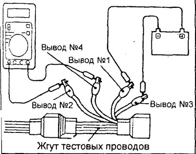
6. Connect a voltmeter to the terminal "2" and to the conclusion "4" oxygen sensor connector.
7. While periodically depressing the accelerator pedal, measure the output voltage of the oxygen sensor. When the air/fuel mixture becomes slightly richer as the engine speed increases (overclocking), a working oxygen sensor should give a voltage of 0.6-1.0 V.
8. If there are defects, replace the oxygen sensor.
9. Disconnect the test harness and connect the connector to the sensor.
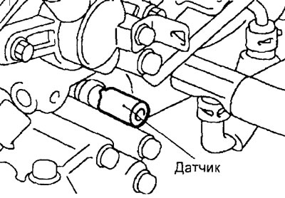
Catalytic converter temperature sensor
1. Disconnect the sensor connector.
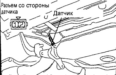
2. Measure resistance between conclusions of a socket of the gauge.
Rated resistance (at 20 C°) - 1 MΩ and above
Note: At 400°C, the sensor resistance should be 3.44 kOhm.
3. If the measured resistance does not correspond to the nominal value, then replace the sensor.
Nozzles
1. Disconnect the intermediate connector of the injectors.
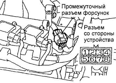
Engine 4G15.
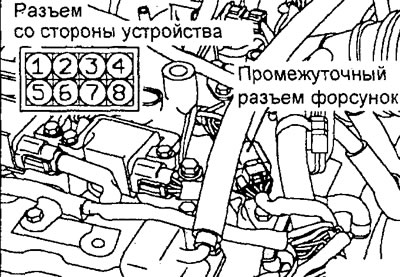
Engine 4G93.
2. Measure the resistance in the injector circuit according to the table below.
Rated resistance (at 20°C) - 0.9-1.1 ohm
| Nozzle | conclusions |
| 1 | "1" - "2" |
| 2 | "3" - "4" |
| 3 | "5" - "6" |
| 4 | "7" - "8" |
3. Connect the intermediate connector of the injectors.
Throttle servo
Checking the operation of the servo
1. Disconnect the air intake hose from the throttle body.
2. Turn on the ignition.
3. Make sure the throttle valve opens and closes according to how the accelerator pedal is depressed.
Winding resistance test
1. Disconnect the throttle servo connector.
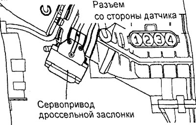
2. Measure the resistance between the leads "1" And "3" and conclusions "2"-"4" throttle servo connector.
Rated resistance (at 20°C) - 1.35-1.65 Ohm
3. Make sure there is no open circuit between each pin and the servo case.
4. If the measured resistance does not correspond to the nominal value, then replace the throttle valve servo.