



Contents: Checking the position of the factory…⤓ Cleaning the throttle body ⤓ Adjusting the throttle position…⤓ Adjusting the accelerator pedal…⤓ Table. Results of checking the fuel…⤓ Checking the fuel system for leaks…⤓ Table. Results of fuel pressure test…⤓ Bleeding residual pressure from the…⤓ Checking the operation of the low…⤓
Checking the position of the factory adjustment screw
Do not touch the factory adjustment screw "Fixed SAS" on the throttle body, the position of which is adjusted with high precision at the factory.
If the factory adjustment of the "Fixed SAS" screw is accidentally violated, the fully closed position of the throttle valve (idle position) will be changed. As a result, the electronic control unit of the engine and variator will be retrained to the incorrect position of the throttle valve.
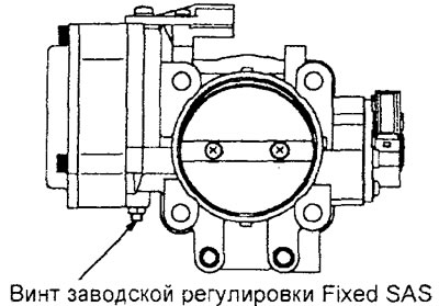
Engine 4G15.
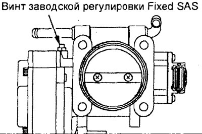
Engine 4G93.
Cleaning the throttle body
1. Start the engine, warm it up to a coolant temperature of 80°C or higher, and then turn off the engine.
(The original can be found on the website: MitsubishiMan.ru)
2. Disconnect the air hose from the throttle body.
3. Spray the recommended detergent cleaner into the throttle body through the intake port and wait for about 5 minutes.
Washing cleaner - Three bond 6601
4. Start the engine. Press the accelerator pedal several times and let the engine idle for 1 minute.
5. If the deposits in the throttle body are not removed, repeat steps "3" and "4".
6. Connect the air hose to the throttle body.
7. Clear fault codes from the memory of the engine and CVT electronic control unit.
Adjusting the throttle position sensor
1. With the ignition off, connect the tester to the diagnostic connector.
2. If the tester is not available, perform the following operations:
a) Disconnect the throttle position sensor connector and connect the test lead harness between the connectors.
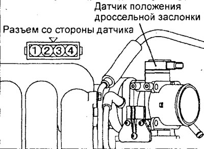
Engine 4G15.
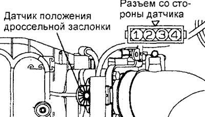
Engine 4G93.
b) Using wires with an alligator clip connector, connect a voltmeter between terminal "2" (sensor signal for channel #1) or "4" (sensor signal for channel #2) and terminal "3" (sensor ground) of the sensor connector.
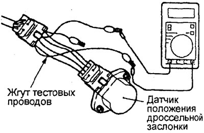
3. Disconnect the throttle servo connector.
4. Turn on the ignition (do not start the engine).
5. Adjusting the throttle position sensor (channel No.1).
a) Manually close the throttle valve completely and measure the signal voltage of the throttle position sensor (channel No.1).
Nominal voltage - 0.4 -0.6V
b) If the measured value does not correspond to the nominal value, loosen the throttle position sensor mounting bolts. Adjust the sensor signal voltage by rotating the sensor housing.
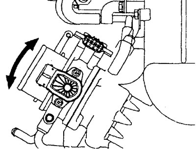
Engine 4G15.
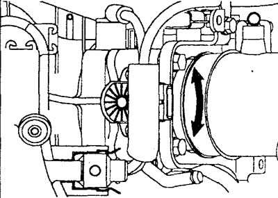
Engine 4G93.
6. Adjusting the throttle position sensor (channel No.2).
a) Manually close the throttle valve completely and measure the signal voltage of the throttle position sensor (channel No.2).
Nominal voltage - 4.2 - 4.8 V
b) If the voltage is not within the normal range, replace the throttle position sensor.
7. Turn off the ignition.
8. If the test was performed without a tester, remove the test wire harness and voltmeter.
9. Connect the throttle servo connector.
10. Clear fault codes from the engine control unit memory.
11. Perform throttle servo retraining.
Turn the ignition switch from the "OFF" position to the "ON" position, then turn the key to the "OFF" position and wait 10 seconds.
12. Disconnect the tester.
Adjusting the accelerator pedal position sensor
Caution: Do not touch the accelerator pedal position sensor unless absolutely necessary. The position of the sensor is adjusted with high precision at the factory. Adjustment is only necessary if the sensor has been incorrectly adjusted at the factory.
1. With the ignition off, connect the tester to the diagnostic connector.
2. If the tester is not available, perform the following operations.
a) Disconnect the accelerator pedal position sensor connector and connect the test lead harness between the connectors.
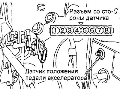
b) Using wires with an alligator clip, connect the voltmeter to terminal "3" (sensor signal for channel No.1) and terminal "1" (sensor ground for channel No.1).
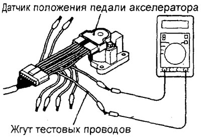
3. Adjusting the accelerator pedal position sensor.
a) Slightly loosen the accelerator pedal position sensor mounting screws.
b) Keep the accelerator pedal in the position where it touches the stopper.
4. Turn on the ignition (do not start the engine).
5. Rotate the sensor around the control pin, and adjust the signal voltage of the accelerator pedal position sensor to match the standard value.
Nominal value - 0.985 - 1.085 V
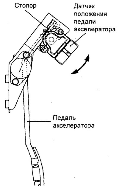
6. Tighten the accelerator pedal position sensor mounting screws.
Checking the fuel pressure in the line between the high-pressure fuel pump and the low-pressure pump
1. To prevent fuel splashing, release residual pressure from the high-pressure line (see the relevant subsection).
2. Disconnect the high pressure fuel hose from the injection pump as shown in the figure.
Caution: Since there is residual pressure in the fuel line, cover the hose connection with a rag to prevent fuel from splashing.
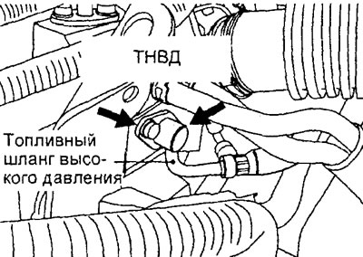
Engine 4G15.
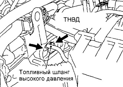
Engine 4G93.
3. Install special devices for measuring pressure.
a) Prepare an adapter (tee) for connection to the high-pressure fuel pump.
b) Connect the adapter between the high pressure fuel hose and the injection pump.
c) Install a pressure gauge or sensor on the adapter. Be sure to install suitable O-rings to prevent fuel leaks.
d) (Checking the pressure with the sensor) Connect the power wire of the pressure sensor to the power source (cigarette lighter), and the signal wire to the tester.
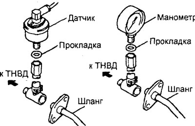
4. Check for leaks after installing the pressure gauge.
a) Connect the tester to the diagnostic connector.
Caution: The tester can only be disconnected or connected when the ignition is off.
b) Turn on the ignition (do not start the engine).
c) Select sub-item #07 of the "ACTUATOR TEST" item of the tester and activate the low-pressure fuel pump in the tank. Make sure there are no fuel leaks at the connection points.
d) Complete the "ACTUATOR TEST" item of the tester and turn off the ignition.
5. Checking the pressure with the fuel pump on (low pressure).
a) Start the engine and let it idle.
b) With the engine idling, measure the fuel pressure in the line.
Nominal value - 324 kPa
c) Check that the fuel pressure at idle speed does not drop even after pressing the accelerator pedal several times (to increase the engine speed).
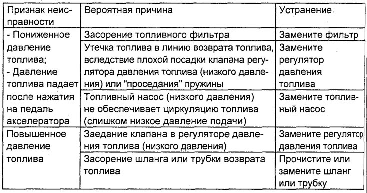
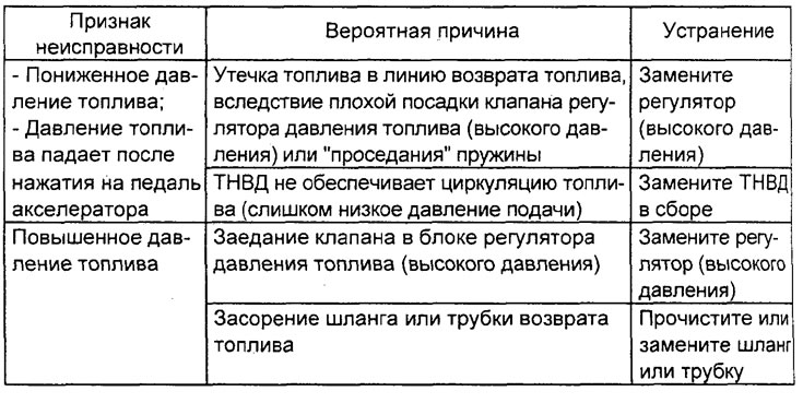
d) If any of the pressure test results are abnormal, troubleshoot and correct them in accordance with the table "Results of checking the fuel pressure in the low-pressure line with the fuel tank pump on".
6. Checking the drop in fuel pressure after turning off the fuel pump.
a) Turn off the engine (turn off the fuel pump) and check for changes in the fuel pressure gauge readings. The fuel system is in good condition if the pressure in the fuel line does not decrease within 2 minutes. If the pressure drops, determine the rate of pressure drop (gradually/instantly) and troubleshoot and eliminate them.
b) If after stopping the engine the fuel pressure drops gradually, there are leaks through the fuel pressure regulator valve (loose valve fit).
c) If the fuel pressure drops immediately after the engine stops, the check valve in the fuel pump remains open all the time (replace the fuel pump).
7. To prevent fuel splashing, release residual pressure from the high-pressure line.
8. Disconnect the special tools assembled from the high-pressure fuel pump and fuel hose.
Caution: Since there is residual pressure in the fuel line, cover the hose connection with a rag to prevent fuel from splashing.
9. Replace the O-ring on the high pressure fuel hose flange with a new one, lubricate the gasket with engine oil before installation.
10. Connect the fuel hose to the high-pressure fuel pump and tighten the mounting bolt to the specified torque.
11. Check for fuel leaks in the same manner as described in point "4".
12. Disconnect the tester.
Checking the fuel pressure in the line between the injection pump and the injectors
Note: the pressure in the high-pressure line (between the high-pressure fuel pump and the injectors) should be measured only after making sure that the fuel pressure between the low-pressure pump in the tank and the high-pressure fuel pump is within the norm.
1. With the ignition off, connect the tester to the diagnostic connector.
2. Disconnect the intermediate connector of the injectors.
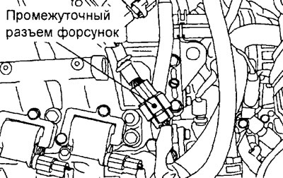
Engine 4G15.
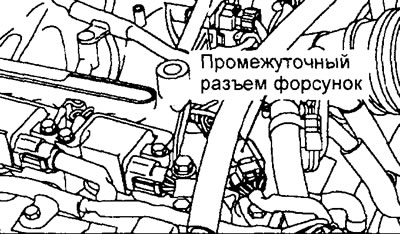
Engine 4G93.
Table. Results of checking the fuel pressure in the low-pressure line with the fuel pump in the tank turned on.
3. Turn the ignition switch to the "ON" position.
4. Select item No.74 from the "SERVICE DATA" menu of the tester (fuel pressure control).
5. Crank the engine crankshaft with the starter for 2 seconds or more and visually check for fuel leaks through the connections.
Caution: If fuel leaks are present, immediately stop cranking the engine with the starter and eliminate the source of the leak.
6. Turn the engine crankshaft with the starter and check the fuel pressure after 20 seconds.
The minimum permissible value is 1 MPa
Caution: If the fuel pressure is less than 1 MPa, there are probably leaks in the high-pressure line - perform the appropriate check.
7. Turn off the ignition.
8. Connect the intermediate connector of the injectors.
9. Checking the fuel pressure in the high-pressure line.
a) Start the engine and let it idle.
b) With the engine idling, measure the fuel pressure in the line.
Nominal pressure - 4-6.9 MPa
c) Check that the fuel pressure does not drop at idle speed, even after pressing the accelerator pedal several times (to increase the engine speed).
d) If any of the pressure test results are abnormal, troubleshoot and correct them in accordance with the table "High-pressure fuel line pressure test results".
10. Turn off the ignition (stop the engine).
11. Disconnect the tester.
Checking the fuel system for leaks (using a tester)
1. Connect the tester to the diagnostic connector.
2. Disconnect the intermediate connector of the injectors.
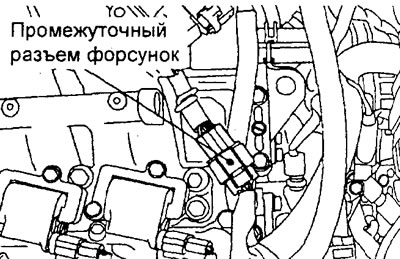
Engine 4G15.
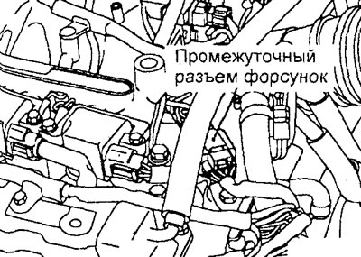
Engine 4G93.
Table. Results of fuel pressure test in high pressure line
3. Turn on the ignition.
4. Select item #74 from the "SERVICE DATA" menu of the tester.
5. Crank the engine crankshaft with the starter for 2 seconds or more and visually check for fuel leaks through the connections.
Caution: If fuel leaks are present, immediately stop cranking the engine with the starter and eliminate the source of the leak.
6. Turn the engine crankshaft with the starter and check the fuel pressure after 20 seconds.
The minimum permissible value is 1 MPa
Caution: If the fuel pressure is less than 1 MPa, there are probably leaks in the high-pressure line - perform the appropriate check.
7. Turn off the ignition.
8. Connect the intermediate connector of the injectors.
9. Disconnect the tester.
Bleeding residual pressure from the high-pressure line (using a tester)
Note: Since the fuel line is under pressure, perform this operation before removing fuel system components (hoses, tubes, etc.) to relieve fuel pressure and prevent fuel splashing.
1. Loosen the fuel tank filler cap to relieve pressure in the tank.
2. Remove the rear seat cushion.
3. Remove the service hole cover and gasket.
4. Disconnect the fuel pump wiring harness connector.
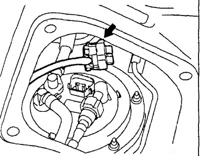
5. With the ignition off, connect the tester to the diagnostic connector.
6. Turn on the ignition and select item No.74 from the "SERVICE DATA" menu of the tester (fuel pressure control).
7. Crank the engine with the starter for 2 seconds or more.
8. If the engine does not start, use a tester to make sure the pressure is less than 0.5 MPa, then turn off the ignition.
9. If the engine starts, release residual pressure from the fuel lines as follows:
- a) Turn off the ignition (stop the engine).
- b) Disconnect the wiring connector of one of the ignition coils.
- c) Crank the engine crankshaft with the starter for 2 seconds or more.
- d) If the engine does not start, use a tester to make sure that the pressure is less than 0.5 MPa and turn off the ignition.
- d) If the engine starts, press the accelerator pedal to increase the crankshaft speed until the engine stalls. Then, using a tester, make sure that the pressure is less than 0.5 MPa and turn off the ignition.
- e) Connect the wiring connector to the ignition coil.
Caution: Clean the spark plug associated with the ignition coil whose connector was disconnected.
10. Disconnect the tester.
11. Connect the fuel pump wire harness connector.
12. Install the gasket and service hole cover.
13. Install the rear seat cushion.
Checking the operation of the low pressure fuel pump
The verification procedure is given in the relevant section of the chapter "Fuel injection system (MPI)".