



GDI Engine Design
The main differences in the design of a GDI engine from a multipoint injection (MPI) engine.
1. Higher compression ratio (about 11-12).
2. Intake manifold of a special shape (with a resonator). The intake channels are straight vertical to ensure the formation of the so-called "reverse vortex" of the air charge in the cylinder, which directs the fuel-air mixture to the spark plug and improves the filling of the cylinders with air.
3. Pistons with a concave bottom, with the help of which the fuel-air mixture is directed to the spark plug area.
4. In addition to the conventional fuel tank pump (low pressure pump), a high pressure fuel pump (HPFP) with a mechanical drive from the camshaft is installed, developing a pressure of 5.0 - 5.5 MPa. For accuracy of dosing, a fuel pressure sensor is installed.
Note: since the normal operation of the high-pressure fuel pump requires thorough fuel cleaning, a multi-stage fuel filtration system is used: in addition to the filter at the pump inlet in the tank and the standard fuel filter, microfilters are installed inside the high-pressure fuel pump.
5. Injectors with vortex atomizers, creating a fuel spray torch of various shapes, depending on the engine operating mode (in the power mode - conical, in the super-lean mixture combustion mode - compact torch). To amplify the signal (voltage 100 V) for controlling the injectors, a former of the control signals of the injectors is installed.
6. Electronically controlled throttle valve (servo drive), controller and using the signal from the accelerator pedal position sensor. The driver does not directly control the valve, but only "activates" the accelerator pedal position sensor. The position of the throttle valve is changed by the electronic control unit, depending on the engine operating conditions and the sensor signals.
7. EGR unit with EGR valve servo drive (stepper motor). EGR is mainly performed when the engine operates in the lean-mixture combustion mode.
8. Separate ignition coil for each spark plug. No high-tension spark plug wires are used.
9. An additional control lamp is installed on the instrument cluster to indicate that the "GDI ECO" mode (super-lean mixture combustion mode) is on.
10. For the electronic control unit of the engine and variator, in addition to the signals of the components marked in the figure "General diagram of the GDI fuel injection system", signals from the ignition switch ("ST" and "IG" terminals), power line, air conditioner switch, air conditioner load, refrigerant pressure sensor, start prohibition switch, power steering hydraulic fluid pressure switch, generator "FR" terminal, brake light switch, electrical equipment control unit, throttle servo controller, accelerator pedal position sensor (channel No.1), accelerator pedal fully released switch and injector circuit open signal (control) are also used.
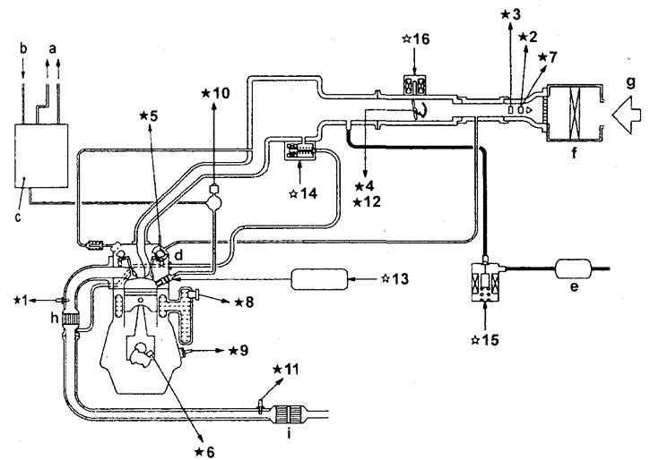
General diagram of the GDI fuel injection system. 1 - oxygen sensor, 2 - mass air flow sensor, 3 - intake air temperature sensor, 4 - throttle position sensor (channel No.2), 5 - camshaft position sensor, 6 - crankshaft position sensor, 7 - atmospheric pressure sensor, 8 - engine coolant temperature sensor, 9 - knock sensor, 10 - fuel pressure sensor, 11 - catalytic converter temperature sensor, 12 - throttle position sensor (channel No.1), 13 - injector control signal generator, 14 - exhaust gas recirculation valve servo drive, 15 - adsorber purge solenoid valve, 16 - throttle valve servo drive; a - into the fuel tank, b - from the low-pressure fuel pump, c - high-pressure fuel pump (HPFP) and fuel pressure regulator (high pressure), d - injector, e - adsorber, f - air filter, g - air, h - preliminary catalytic converter (on the exhaust manifold), i - main catalytic converter (under the floor of the car body).
Note: The signals of the components marked are used by the engine control unit; marked with " ☆ " are actuators.
11. The actuators are, in addition to the components noted, the relay (No. 1 and No.2) of the fuel pump in the tank, the main relay of the injection system, the relay of the electromagnetic clutch of the air conditioning compressor, the indicator "CHECK ENGINE", the self-diagnosis circuit, the ignition coils, the "G" terminal of the generator, the heating element of the oxygen sensor, the injector control relay, the throttle servo relay, the throttle servo controller, the indicator of the "GDI ECO" mode, the controller of the electric fans.
12. The signal from the throttle position sensor (channel #1) is used by the throttle servo controller. Signals from the power line, the accelerator pedal position sensor (channel #2) and the electronic control unit of the engine and variator are also used.
GDI engine operating modes
To precisely control the combustion process, the GDI engine uses three fuel delivery modes.
Note: a - air/fuel ratio.
1. Ultra-lean mixture combustion mode ("GDI ECO" mode).
This mode operates when the car is moving at a constant speed (up to 120 km/h) or the engine is idling. Fuel is injected at the end of the compression stroke by a compact torch, reflected from the piston bottom and directed to the spark plug area. Although in the main volume of the combustion chamber the mixture is extremely lean (a ~ 30-40), the charge in the spark plug area is rich enough to ignite from a spark and ignite the rest of the mixture.
Note: When the engine is running in this mode, the "GDI ECO" mode indicator lights up on the instrument cluster.
2. Power mode.
This mode operates when the car is moving at high speed or accelerating. Fuel is injected during the intake stroke, mixing with air and forming a uniform (homogeneous) mixture, as in a conventional engine with distributed injection. The composition of the mixture is close to stoichiometric (a ~ 15).
3. Two-stage mode (applies only to left-hand drive models).
a) This mode is used when the car accelerates intensively to provide maximum torque at low revs. First, a smaller portion of fuel is injected on the intake stroke, cooling the air and creating an ultra-lean mixture (a ~ 60). Then, on the compression stroke, a larger portion of fuel is injected and the mixture is significantly enriched (a ~ 12). When the mixture is burned, high engine power and torque are achieved,
b) This mode (in combination with a specially designed exhaust manifold) can be used to quickly warm up the three-way catalytic converter after starting the engine.