Contents: General information ⤓ Checking the "CHECK ENGINE" indicator ⤓ Clear diagnostic trouble codes…⤓ Checking using the "SERVICE DATA"…⤓ Current engine status data ("freeze…⤓ Table. "Freeze frame" of data. ⤓ Checks on the connector of the…⤓ Checking the voltage at the…⤓ Checking the resistance status at…⤓ Table. Diagnostic trouble codes. ⤓ Table. Checking the voltage at the…⤓ Table. Checking the resistance at…⤓ Table. Checking the voltage at the…⤓ Table. Checking injection system…⤓ Table. Checking the injection system…⤓
Note: The procedure for reading diagnostic trouble codes using a tester and the procedure for diagnosing a vehicle are given in the corresponding section of the chapter "Fuel injection system (MPI)".
General information
The procedure is given in the relevant section of the chapter "Fuel injection system (MPI)".
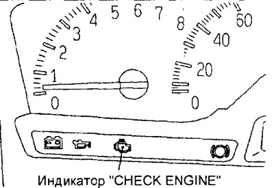
Checking the "CHECK ENGINE" indicator
1. Turn on the ignition (key in the lock to the "ON" position) and make sure that the "CHECK ENGINE" indicator lights up for about 5 seconds and then goes out.
2. If the indicator does not light, check the wiring, fuse and indicator lamp.
3. If the indicator remains on after starting the engine or lights up when the engine is running, check for fault codes. The indicator lights up when the self-diagnosis system detects a fault in the electronic control unit of the engine and variator, a fault in one of the sensors of the fuel injection system (GDI) or injectors, a fault in the immobilizer, a fault in the throttle control system, incorrect fuel pressure, abnormal combustion, excessive amount of air at the intake, etc.
Note: The indicator will illuminate if the throttle control system is disabled.
Clear diagnostic trouble codes without a tester
Note: After repair, clear the fault codes from the ECU memory.
1. Turn off the ignition (key in the "OFF" position).
2. After disconnecting the cable from the negative battery terminal for 10 seconds or more, reconnect the cable to the terminal.
3. Start the engine and let it idle for 10 minutes or more.
Checking using the "SERVICE DATA" and "ACTUATOR TEST" functions of the tester
1. Perform a test using the "SERVICE DATA" and "ACTUATOR TEST" functions of the tester. If a fault is detected, check the vehicle's electrical wiring, relevant units and components.
2. After repair, re-test with a tester and make sure that the repair has made the abnormal input and output signal normal (conform to the standard).
3. Clear diagnostic trouble codes from the engine control unit memory.
4. Start the engine and road test it to ensure that the problem has been corrected.
Current engine status data ("freeze frame")
If multiple faults are detected, the ECU memory will store a freeze frame of data only for the fault detected first. The freeze frame data table lists the components whose status information will be written to the ECU memory if a fault is detected.
Table. "Freeze frame" of data.
| № | Parameter | Unit of measurement. |
| 12 | Mass Air Flow Sensor | Hz |
| 13 | Intake Air Temperature Sensor | °C |
| 21 | Engine Coolant Temperature Sensor | °C |
| 22 | Crankshaft position sensor | rpm |
| 24 | Vehicle speed sensor | km/h |
| 44 | Ignition timing angle | ° before TDC |
| 81 | Long-term fuel balance | % |
| 82 | Short-term fuel balance | % |
| 87 | Calculated load | % |
| 8A | Throttle Position Sensor (Channel #1) | % |
| A1 | Oxygen sensor | mV |
Checks on the connector of the electronic control unit of the engine and variator
Note:
- If any deviation from the nominal value is detected, check the corresponding sensor, actuator and corresponding wires.
- After repairing or replacing a component, retest to ensure that the problem has been corrected.
Checking the voltage at the connector terminals from the electronic control unit side
1. Disconnect the ECM/CVT connector and connect the test lead harness between the connectors or use the voltmeter needle probes to test at the harness side of the connector.
Caution: A short circuit of the positive probe connected to the connector terminal to ground may cause damage to the wiring, sensor, electronic control unit, or all of the above.
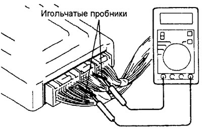
2. With the electronic control unit connector connected, measure the voltage between the ground terminals of the control unit and each corresponding terminal of the unit connector.
3. The terminals and values to be checked are indicated in the table "Checking the voltage at the terminals of the connector of the electronic control unit of the engine and variator".
4. The location of the terminals is shown in the corresponding figures.
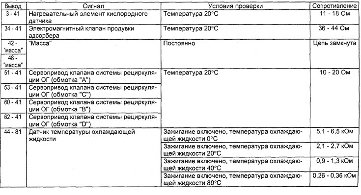
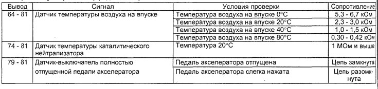
Checking the resistance status at the terminals of the electronic unit connector on the wiring harness side
1. Before starting the check, turn the ignition key to the "OFF" position and disconnect the ECU connector.
2. Connect the test lead harness to the connector on the harness side, then check the resistance and continuity between the connector terminals.
Attention:
- Do not use needle ohmmeter probes.
- If the terminals being tested are mixed up, or the terminals are incorrectly connected to ground, this may result in damage to the wiring, sensors, electronic control unit and/or ohmmeter.
3. The terminals and values to be checked are indicated in the table "Checking the resistance at the terminals of the electronic control unit connector on the wiring harness side".
4. The location of the terminals is shown in the corresponding figure.
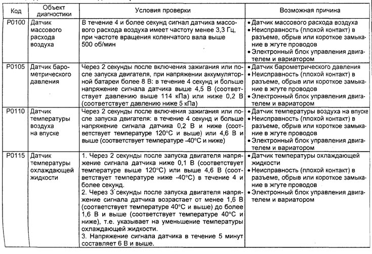
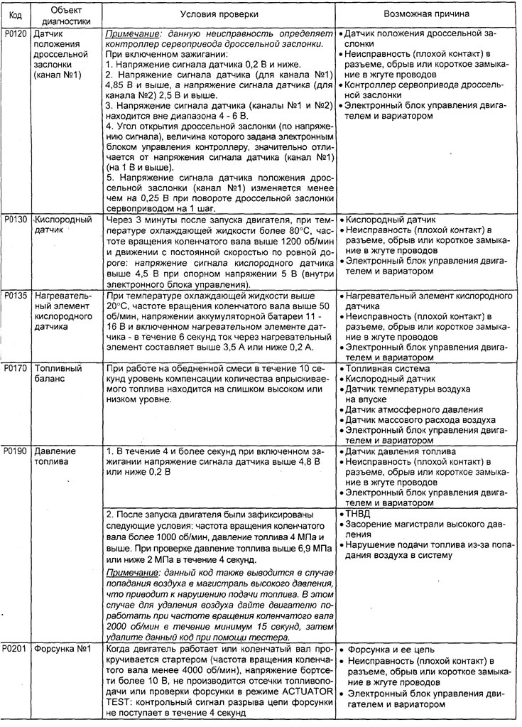
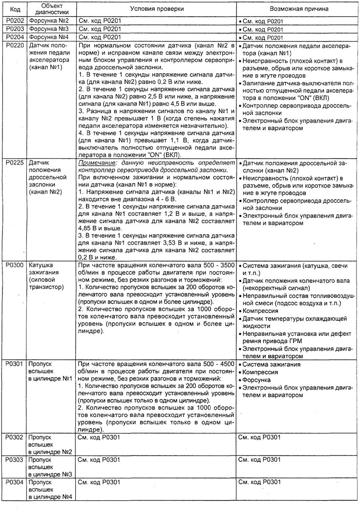
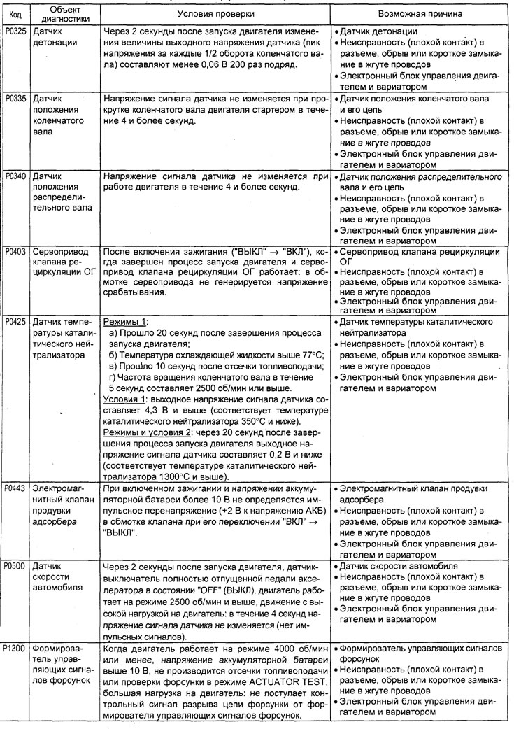
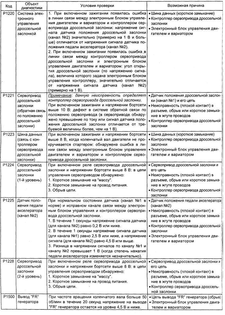
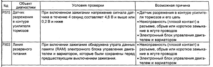
Table. Diagnostic trouble codes.

Connector from the side of the electronic control unit of the engine and variator.
Table. Checking the voltage at the terminals of the electronic control unit of the engine and variator.
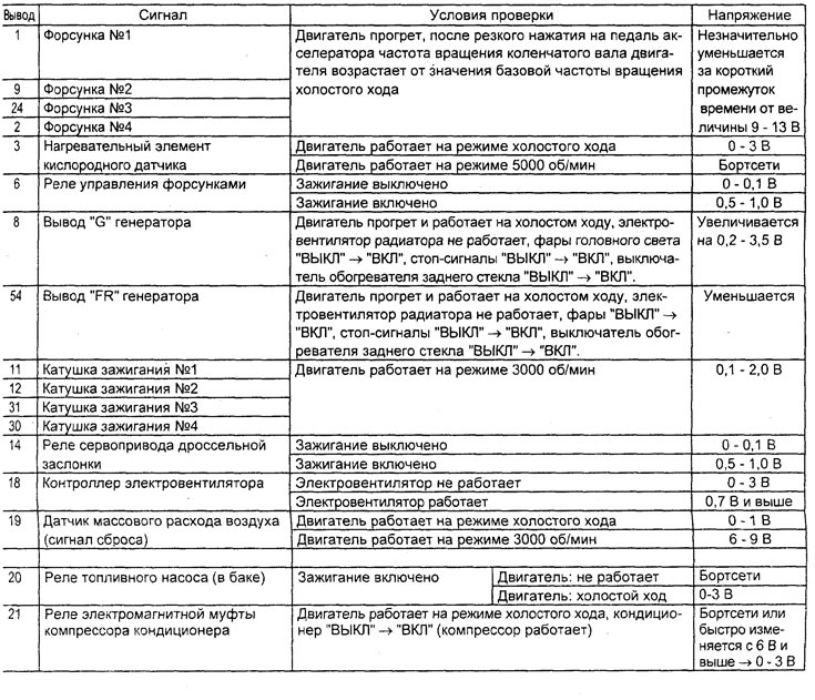
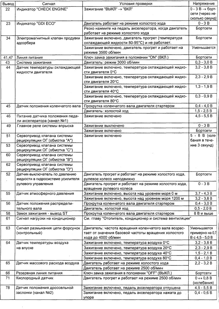
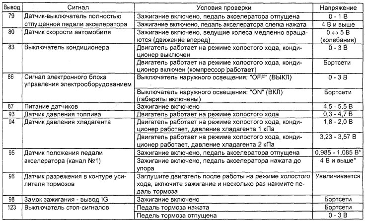
Note: The "*" symbol in the table indicates that for the accelerator pedal position sensor (channel #1), it is necessary to check the difference between the values at different accelerator pedal positions.

Connector of the electronic control unit of the engine and variator from the side of the wiring harness.
Table. Checking the resistance at the terminals of the connector of the electronic control unit of the engine and variator from the side of the wiring harness.
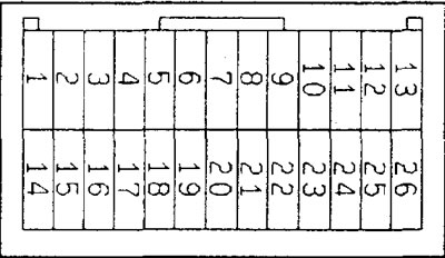
Connector on the throttle servo controller side.
Table. Checking the voltage at the terminals of the throttle servo controller.
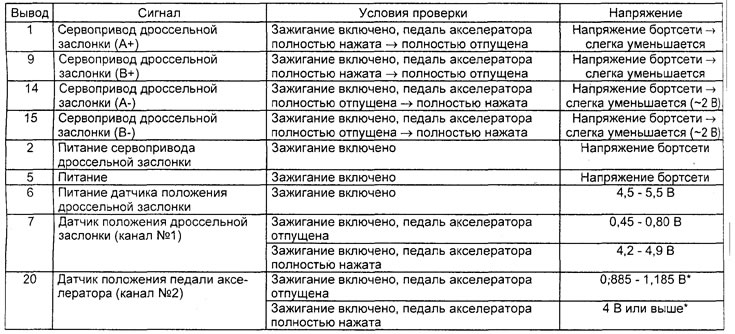
Note: the "*" symbol in the table indicates that for the accelerator pedal position sensor (channel #2), it is necessary to check the difference between the values at different accelerator pedal positions (should be at least 4 V).
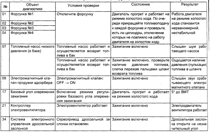
Table. Checking injection system components using the "SERVICE DATA" function of the tester.
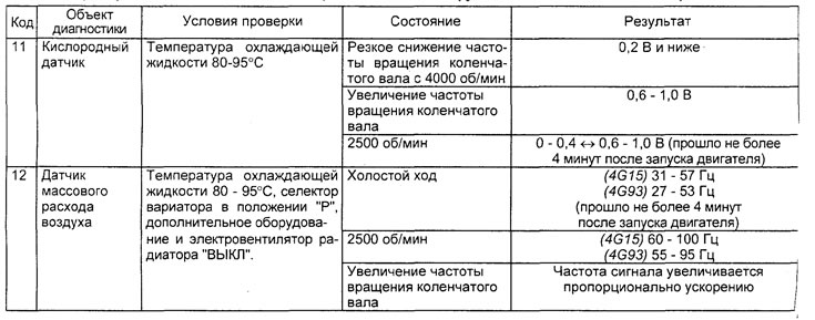
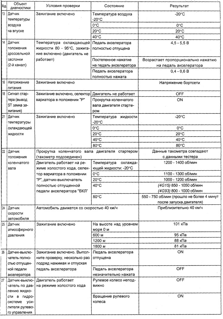
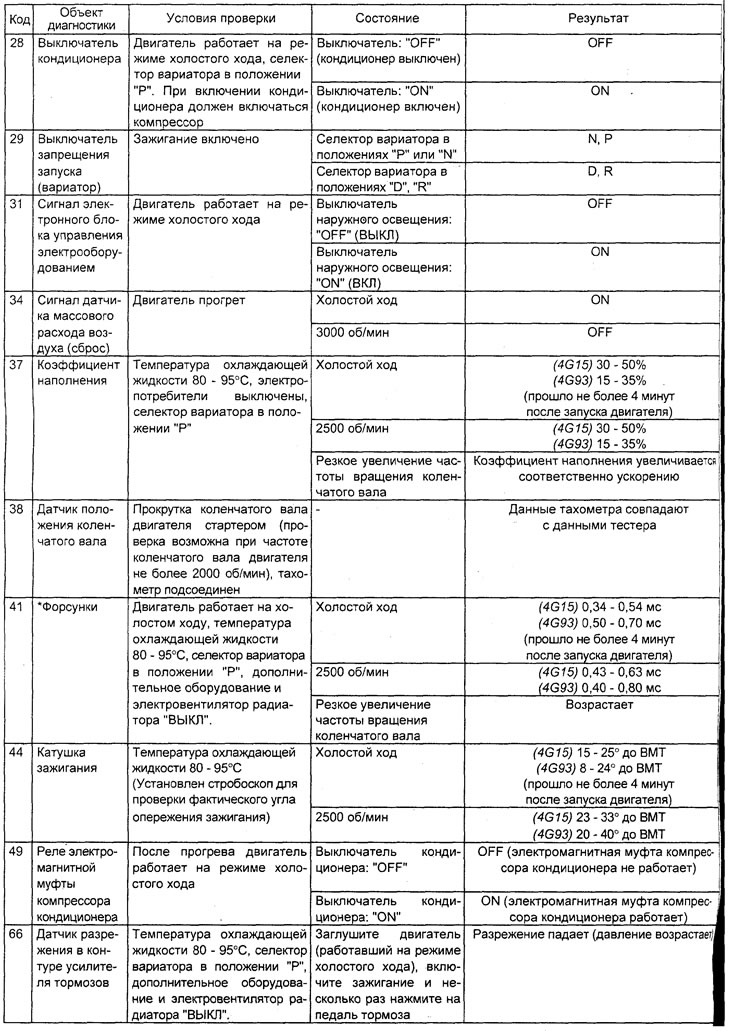
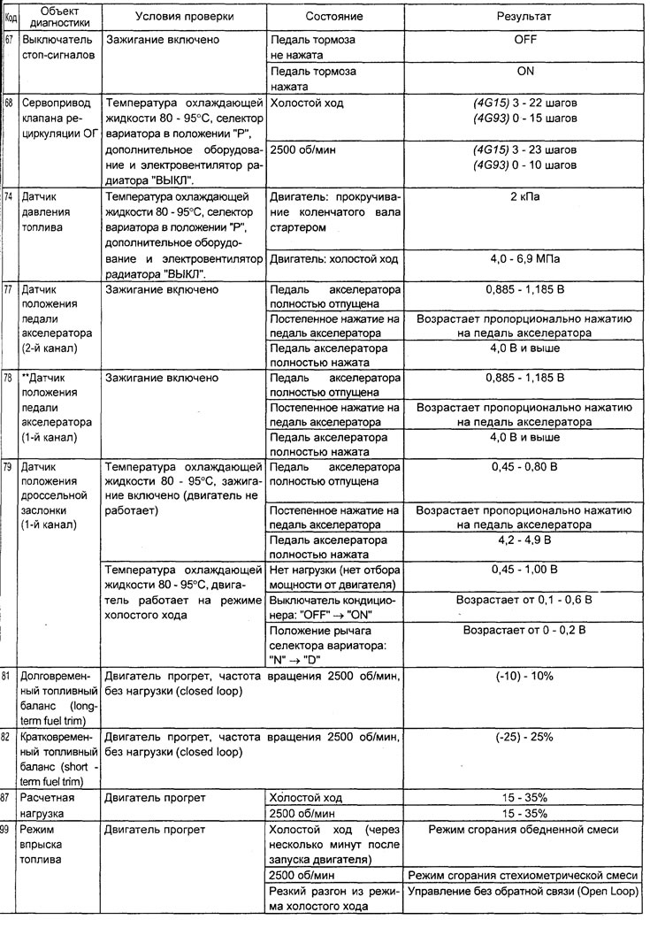
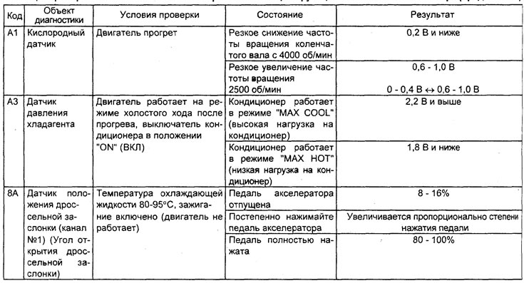
Note:
- When moving the CVT selector to position D, it is necessary to keep the brake pedal fully depressed to prevent the vehicle from moving forward;
- -"*"-On a new car (with a mileage of 500 km or less), the result may sometimes differ by 10% upwards from the nominal value.
- -"*"-When the signal voltage of the accelerator pedal position sensor (channel #1) is 1.185-1.685 V, the fully released accelerator pedal switch should move from the "ON" position to the "OFF" position. If the signal voltage of the sensor changes after the accelerator pedal has been fully released, the fully released accelerator pedal switch and the accelerator pedal position sensor (channel #1) must be adjusted.
Table. Checking the injection system components using the "ACTUATOR TEST" function of the tester.