



Note: The procedures for replacing the fuel level sensor and fuel pump are provided in the "Fuel tank" chapters "Fuel injection system (MPI)".
Removal and installation
− Before you begin removing parts, perform the following operations:
- a) Drain the fuel from the tank.
- 6) Release residual pressure from the high-pressure fuel line.
- c) Remove the central pipe of the exhaust system.
- d) (4WD models) Remove the propeller shaft.
− The parts are removed in the order of the numbers indicated in the figures "Removing the fuel tank" and "Removing the fuel tank filler neck".
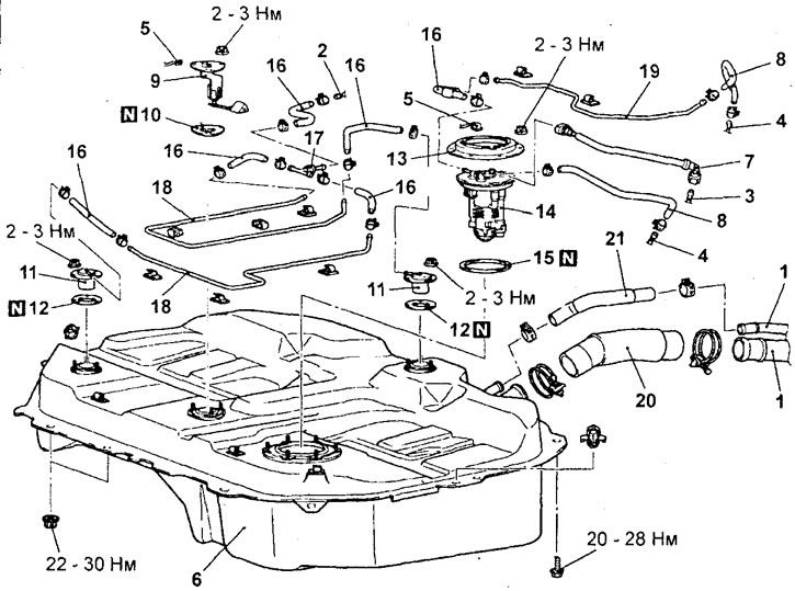
Removal the fuel tank. 1 - Fuel tank drain pipe and filler neck connection 2 - Evaporative emission system pipe connection 3 - Fuel pipe connection 4 - Fuel return pipe connection (disconnect the left parking brake cable retainer, the rear right wheel speed sensor wiring harness retainer and the sensor wiring harness connector), 5 - Wire harness connector, 6 - Fuel tank assembly, 7 - Fuel hose, 8 - Fuel return hose, 9 - Fuel level sensor, 10 - Gasket, 11 - Fuel shut-off valve, 12 - Gasket, 13 - Cap, 14 - Fuel pump assembly 15 - Gasket, 16 - Evaporative emission system hose, 17 - Check valve, 18 - Evaporative emission system pipe, 19 - Return pipe fuel, 20 - fuel tank filler hose, 21 - drain hose.
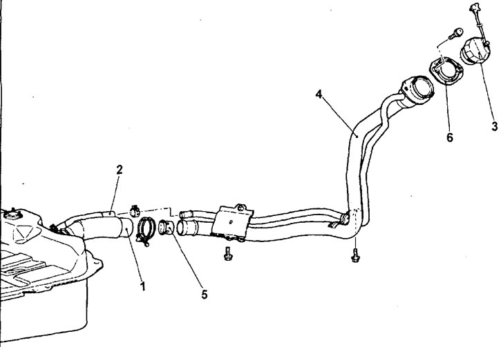
Removal the fuel tank filler neck. 1 - filler neck hose connection, 2 - drain hose connection, 3 - fuel tank filler cap, 4 - fuel tank filler, 5 - fuel tank filler valve, 6 - gasket.
− When removing parts, pay attention to the operation of disconnecting the fuel tank wiring harness connector.
Partially lower the fuel tank, then disconnect the wire harness connector.
− Installation is carried out in the reverse order of removal.
- When installing the parts, pay attention to the fuel hose installation operation.
To connect the fuel hose, push the hose connector onto the pipe until the connector lock catches the pipe protrusion. Then pull the connector slightly in the direction of disconnection to ensure that the connection is secure. Check that the play in the connection does not exceed 3 mm.
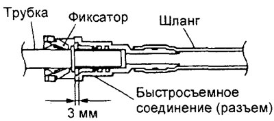
- After completing the installation of the parts, perform the following operations:
- a) (4WD models) Install the driveshaft.
- b) Install the central pipe of the exhaust system.
- c) Fill the tank with fuel.
- d) Check the tightness of the fuel line connections.
Examination
Note: The testing procedures are similar to the corresponding procedures given in section "Fuel tank" chapters "Fuel injection system (MPI)".
Disassembly and assembly of the fuel pump unit
− The parts are removed in the order of the numbers indicated in the figure "Disassembling the fuel pump unit".
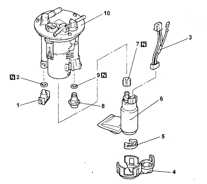
Disassembling the fuel pump unit. 1 - cover, 2 - ring gasket, 3 - fuel pump wire harness connector, 4 - bracket, 5 - buffer, 6 - fuel pump (low pressure), 7 - sealing sleeve, 8 - fuel pressure regulator (low pressure), 9 - ring gasket, 10 - fuel filter assembly.
− Installation is carried out in the reverse order of removal.
- When installing the parts, pay attention to the operation of installing the O-ring and sealing sleeve.
Apply a small amount of fuel to the O-ring and sealing grommet to prevent damage or twisting.