
Main characteristics of the system
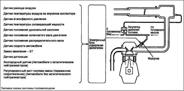
The multiport fuel injection system consists of sensors that record the state of the engine, an electronic engine control unit (engine-ECU), which performs control functions based on sensor signals, and actuators operating on commands from the control unit.
Fuel injection control (fuel supply)
The fuel delivery system used on Mitsubishi Motors vehicles is designed to provide precise fuel metering that provides the best balance between power output, fuel efficiency and low emissions.
In fuel supply systems, the ECM receives signals from the relevant sensors and controls the fuel injectors in such a way as to provide the best air-fuel mixture in various engine conditions. When changing operating modes, the fuel system immediately adapts to them.
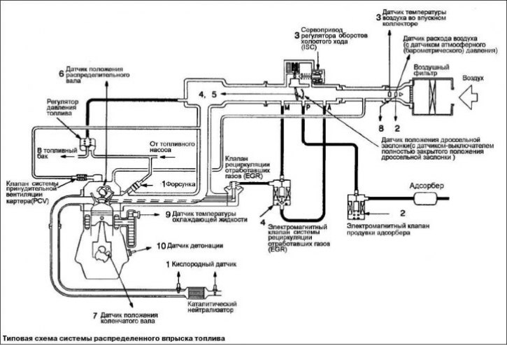
The moment of injector opening and the duration of its open state are set in such a way that the engine receives an air-fuel mixture of optimal composition, corresponding to continuously changing engine operating conditions. The injector is mounted on the inlet pipe of each cylinder. Fuel is supplied by the fuel pump from the fuel tank to the fuel manifold under pressure, the value of which is maintained by the pressure regulator. In the fuel manifold, fuel, under a certain pressure, is distributed to each nozzle. Under normal conditions, fuel is injected once every two revolutions of the crankshaft for each cylinder.
The control unit controls fuel injection, idle speed and ignition timing. In addition, the control unit has a number of diagnostic modes of operation to simplify troubleshooting.
The order of operation of cylinders 1-3-4-2. This mode is called sequential fuel injection. The electronic control unit ensures the enrichment of the air-fuel mixture during engine warm-up, as well as during operation at maximum load, exercising control without feedback on the composition of the mixture («open-loop»).
If the engine is warm or running in partial modes, then the control unit ensures that the stoichiometric (theoretically necessary for the complete combustion of fuel) composition of the air-fuel mixture, exercising feedback control («closed-loop») on the composition of the mixture using the signals of the oxygen sensor. This ensures maximum efficiency of the three-way catalytic converter.
Secondary air control (idle speed control)
The electronic engine control unit maintains the optimum idle speed, depending on external conditions and engine load, by regulating the amount of air entering the engine through the bypass passage, bypassing the throttle valve. The engine control unit controls the idle speed control servo (ISC), ensuring the maintenance
set speed depending on the temperature of the coolant and the load from the air conditioner. In addition, when the air conditioner is turned on and off at idle, the idle speed controller stepper motor (ISC) doses the amount of additional air in such a way as to exclude fluctuations in the speed of the crankshaft.
Ignition timing control
A power transistor connected to the primary circuit of the ignition coil closes and opens the circuit. In this way, the optimal control of the ignition timing is carried out in accordance with the operating mode of the engine.
The electronic engine control unit determines the optimum ignition timing depending on the engine speed, the volume flow of air entering the engine, the temperature of the coolant and atmospheric pressure.
Self-diagnosis function
If a malfunction occurs in the operation of one of the sensors or actuators related to exhaust gas toxicity reduction systems, the engine malfunction indicator lamp lights up on the instrument panel («CHECK ENGINE»), warning the driver of a malfunction.
If the electronic control unit registers a malfunction in the operation of one of the sensors or actuators, then the unit issues the appropriate diagnostic trouble code.
Recorded in RAM (RAM) electronic control unit data related to sensors and actuators (fault codes), can be read using the MUT-II. In addition, in a certain mode of operation of the MUT-II, forced control of the drives is possible.
Other control functions
The fuel pump control activates the fuel pump relay, which supplies current to the pump motor.
The A/C relay control turns the A/C compressor magnetic clutch relay on and off.
The fan relay control regulates the speed of the cooling system radiator fan and A/C condenser fan depending on the coolant temperature and vehicle speed.
Ignition system
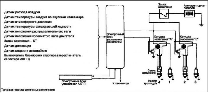
To ensure efficient combustion, the ignition system must ignite the air-fuel mixture in the engine cylinder at a certain moment. A correctly selected ignition timing ensures that the heat released and the pressure developed in the cylinder as a result of combustion are released at the optimum moment according to the position of the piston. The electronic engine control unit receives signals from the relevant sensors and controls the ignition timing.
Air flow control system
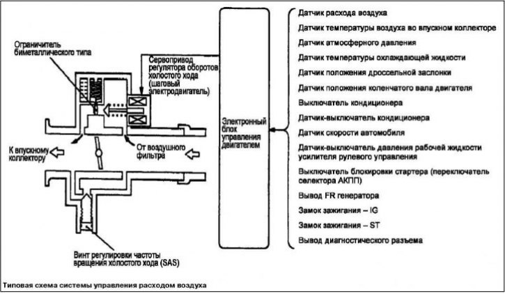
The air flow control system consists of an air flow measurement system and an idle speed control system. The air flow sensing system ensures that the air flow is optimally adjusted when the vehicle is moving under normal conditions by changing the throttle position.
The idle speed control system regulates the air flow through the intake system when the throttle is fully closed. This system monitors engine speed and throttle position along with other inputs.
Emission Control System
Emissions Control Systems Needed to Monitor Hydrocarbon Content (CH), carbon monoxide (SO), and nitrogen oxides (NOx). The following systems are installed on Mitsubishi Motors vehicles to reduce the emission of harmful components in exhaust gases.
Forced crankcase ventilation system (PCV)
Gases from the combustion chamber through the piston rings enter the crankcase. These leaked gases (bloW-by gases) harmful if released into the atmosphere.
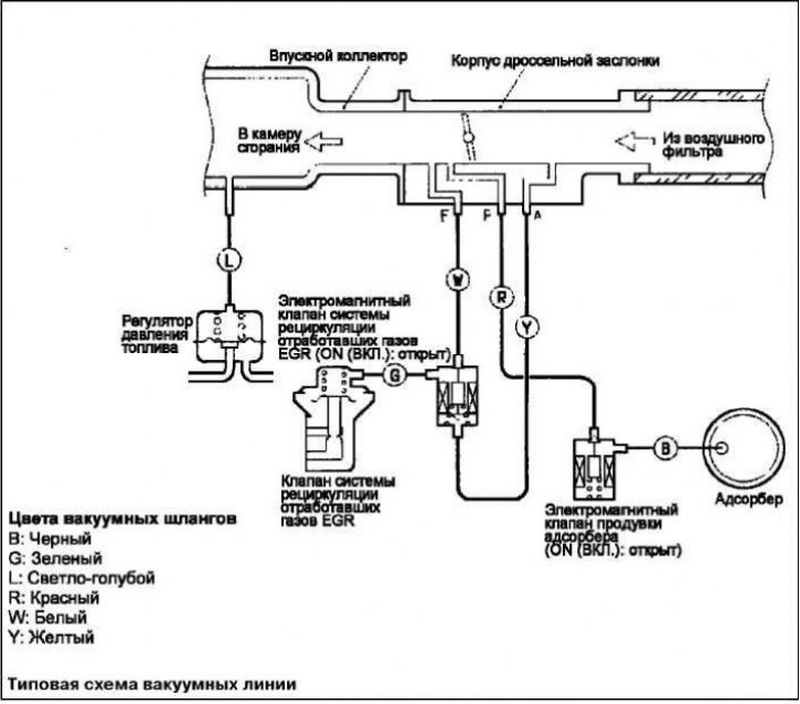
Positive crankcase ventilation valve (PCV valve) is the main element of this system, it passes crankcase gases into the intake manifold, where they, mixing with the air-fuel mixture, are sent to the engine combustion chamber.
Evaporative Emission System
The Evaporative Emission System accumulates fuel vapors that contain a high concentration of hydrocarbons (CH) and come from the fuel tank to the storage adsorber.
Fuel vapors are held in it until they mix with intake air and burn in the engine's combustion chamber.
Exhaust gas recirculation system (EGR)
The exhaust gas recirculation system, in some engine operating modes, takes part of the exhaust gases from the exhaust manifold and sends them to the intake manifold to reduce the temperature in the combustion chamber.
Nitrogen oxides (NOx) are formed in gases as a result of combustion of mixtures at high temperatures.
Catalytic converter
The catalytic converter helps to reduce the content of harmful components, being, in fact, the second combustion chamber. The catalyst helps to carry out chemical reactions in order to prolong the afterburning processes in the exhaust gases, which significantly reduces the content of harmful components in them. The catalytic converter works particularly well when the correct air-fuel ratio is maintained.
To control the operation of the exhaust gas toxicity control system, an on-board diagnostic system is installed on some car models (OBD).