



After this, the electronic engine control unit sends a signal of the set value of the throttle valve opening angle to the throttle valve controller. The throttle valve servo drive, acting on the throttle valve, opens it to an angle preset by the electronic engine control unit.
The system maintains the idle speed at a certain level by changing the air flow rate passing through the throttle valve, according to the state of the engine at idle and the load on the engine at idle.
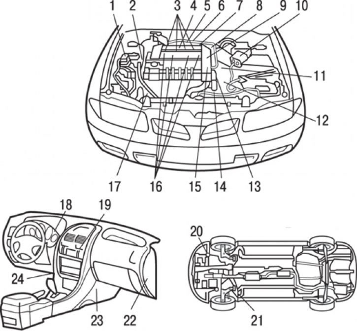
Fig. 8.1. Location of injection system components (GDI): 1 – air conditioning compressor electromagnetic clutch relay; 2 – crankshaft position sensor; 3 – injectors; 4 – knock sensor; 5 – injector control signal generator; 6 – relay for injector control signal generator; 7 – electromagnetic valve for purging the adsorber; 8 – throttle position sensor; 9 – throttle servo; 10 – air flow meter sensor (together with built-in sensors for atmospheric (barometric) pressure and air temperature in the intake manifold); 11 – vehicle speed sensor; 12 – starter lock switch (automatic transmission); 13 – fuel pressure sensor; 14 – coolant temperature sensor; 15 – camshaft position sensor; 16 – ignition coil; 17 – hydraulic power steering system fluid pressure switch; 18 – GDI ECO control lamp; 19 – Air conditioning switch; 20 – oil temperature sensor in a manual transmission (MT); 21 – oxygen sensor; 22 – throttle controller; 23 – Electronic engine control unit; 24 – accelerator pedal position sensor (1st and 2nd channels)
The electronic engine control unit operates the throttle servo so that the idle speed remains constant within a specified value. This value is determined depending on the coolant temperature and the air conditioner load. The arrangement of the direct fuel injection (GDI) system components is shown in Fig. 8.1.