



Contents: Adjusting the base idle speed ⤓ Checking fuel pressure ⤓ Checking the control relay circuit…⤓ Checking the coolant temperature…⤓ Checking the Throttle Position…⤓ Checking the fully closed throttle…⤓ Checking the front oxygen sensor ⤓ Checking the rear oxygen sensor ⤓ Change in resistance between…⤓ Checking the spray pattern of the…⤓ Checking the idle speed control…⤓ Checking winding resistances ⤓
Adjusting the base idle speed
Note: The nominal idle speed is adjusted at the factory by the idle speed adjustment screw (SAS) and usually does not require further adjustment during operation.
If the factory setting has been violated by mistake, a significant increase in idle speed may occur, or it may drop when an additional load is applied to the engine (for example, an air conditioning compressor). If this happens, the adjustment is made as described below.
Before adjusting, check that the spark plugs, injectors, idle speed controller (ISC) are in good condition, that the compression in the cylinders is within the range from the nominal to the maximum permissible value, and that the difference in compression between the cylinders does not exceed the maximum permissible value.
Before checking and adjusting, prepare the vehicle for checking (warm up the engine to normal coolant temperature).
Connect the MUT-II to the diagnostic connector (16-pin).
Note: When connecting the MUT-II, the diagnostic output must be connected to ground.
Start the engine and set it to idle speed.
Select item #30 from the Actuator test menu of the MUT-II tester.
Note: This holds the ISC servo motor at the base idle position, allowing it to be adjusted.
Check the crankshaft speed at idle.
Nominal value: 750±50 min⁻¹.
Note: On a new vehicle (with a mileage of no more than 500 km), the idle speed may be 20–100 min⁻¹ lower than the nominal value, but adjustment is not required in this case.
If the engine stalls or the idle speed is too low on a car with a mileage of more than 500 km, then there is probably a deposit of foreign particles on the throttle valve, so it needs to be cleaned.
The source of the article is available at [MitsubishiMan]
If the idle speed differs from the nominal value, adjust it by turning the idle speed adjustment screw (SAS).
Note: If the idle speed is higher than the nominal speed even with the idle speed adjustment screw (SAS) fully screwed in, check whether the paint on the throttle lever stop screw is damaged ("Fixed SAS", i.e. whether it was previously adjusted). If the paint is damaged, adjust the position of the throttle lever stop screw ("Fixed SAS").
Press the "C" (Clear) MUT-II button to exit the "Accelerator test" mode (forced control of executive devices).
Note: If the "Аctuator test" mode is not cancelled, forced control of the actuators (idle speed control servo) will continue for 27 minutes.
Turn the ignition key to the "OFF" position
Disconnect MUT-II.
Start the engine and let it idle for about 10 minutes, then check that the engine idles normally.
Checking fuel pressure
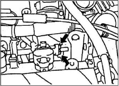
To prevent fuel splashing, relieve residual pressure from the high pressure fuel line.
Disconnect the high pressure fuel hose flange from the fuel rail.
Caution: Cover the high-pressure hose flange connection with the fuel rail with a rag to prevent fuel from splashing due to residual pressure in the high-pressure line.
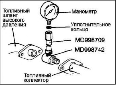
Disconnect the coupling and bypass bolt from the special tool (MD 998709 adapter hose) and connect the special tool (MD 998742 hose adapter) instead. Screw the fuel pressure gauge into the adapter hose assembled earlier. In doing so, be sure to install a suitable sealing ring (gasket) between the pressure gauge nipple and the special tool to prevent fuel leaks.
Install the special tool between the fuel rail and the high pressure fuel hose flange.
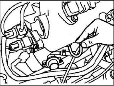
Using a wire with an alligator clip, connect
the positive (+) terminal of the battery with the terminal of the 2-pin service connector of the fuel pump, as shown in the figure, thereby turning on the latter. Check (if there is pressure in the high-pressure line) for fuel leaks at the joints of the pressure gauge and special tools.
To stop the fuel pump, disconnect the alligator clip cable from the battery.
Start the engine and let it idle.
With the engine idling, measure the fuel pressure.
Nominal value: approximately 265 kPa at base idle speed.
Disconnect the vacuum hose from the fuel pressure regulator, cover its opening with your finger and measure the pressure.
Nominal value: 324–343 kPa at base idle speed.
Check that the fuel pressure at idle does not drop even after pressing the accelerator pedal several times.
While pressing the accelerator pedal several times in a row, lightly pinch the fuel return hose with your fingers to feel the presence of fuel pressure in the hose.
Note: If fuel consumption is low, there will be no pressure felt in the fuel return hose.
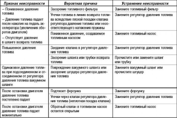
Note: If any of the fuel pressure test results are abnormal, troubleshoot and correct the problem according to the table below.
Turn off the engine and check for changes in the fuel pressure gauge readings.
The fuel system is in good condition if the pressure in the fuel line does not decrease within 2 minutes. If the pressure drops, then search for the fault and eliminate it in accordance with the table.
Release residual pressure in the high pressure fuel line.
Disconnect the pressure gauge and special tool from the fuel manifold.
Caution: Cover the hose flange and adapter connections with a rag to avoid fuel splashing due to residual fuel pressure in the high-pressure line.
Replace the O-ring on the high-pressure hose flange with a new one. Before installing, be sure to lubricate the O-ring with clean engine oil.
Install the high pressure fuel hose pipe flange into the fuel rail and tighten the flange mounting bolts to the specified torque.
Tightening torque: 5 Nm
Check for fuel leaks.
To turn on the fuel pump, connect the terminal of the fuel pump service connector to the "+" terminal of the battery.
Check for leaks in the fuel line while it is under pressure.
Checking the control relay circuit and the fuel pump relay
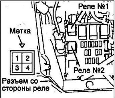
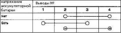
Checking the intake manifold air temperature sensor
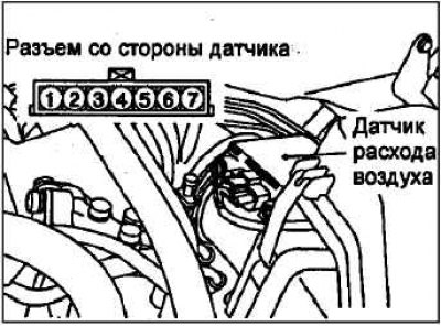
Disconnect the air flow sensor connector.
Measure the resistance between terminals 5 and 6.
Nominal value: 2.3–3.0 kOhm (at 20°C); 0.30–0.42 kOhm (at 80°C).
Measure the resistance by heating the sensor with a hair dryer.
In good condition

If the resistance does not correspond to the nominal value or it does not change depending on the temperature, replace the air flow sensor.
Checking the coolant temperature sensor
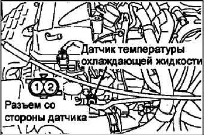
Remove the coolant temperature sensor.
Attention! When removing and installing the sensor, do not touch its connector (plastic part) with the tool.
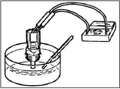
Place the sensitive element of the sensor in hot water and measure the resistance.
Nominal value: 2.1–2.7 kOhm (at 20°C); 0.26–0.36 kOhm (at 80°C).
If the resistance value differs significantly from the nominal value, replace the sensor.

Apply sealant to the sensor threads.
Recommended Sealant: 3M NUT Locking Part # 4171 or equivalent
Install the coolant temperature sensor and tighten it to the specified torque.
Nominal tightening torque: 30 Nm.
Connect the connector to the sensor.
Checking the Throttle Position Sensor (TPS)
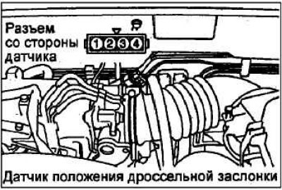
Disconnect the throttle position sensor connector. Measure the resistance between terminals 1 and 4 of the connector on the sensor side.
Nominal value 3.5–6.5 kOhm.
Measure the resistance between terminals 2 and 4 of the connector on the sensor side.
Slowly open the throttle valve from the fully closed (idle) position to the fully open position. The sensor is OK if the resistance changes smoothly in proportion to the throttle opening angle.
If the resistance is outside the nominal range or does not change smoothly, replace the throttle position sensor.
Checking the fully closed throttle position switch
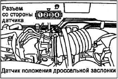
Disconnect the throttle position sensor connector.
Check the circuit between terminals 3 and 4 of the connector on the throttle position sensor side.
In good condition
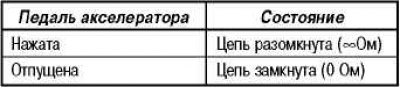
If the circuit conditions are not as specified above, replace the throttle position sensor.
Note: After replacement, it is necessary to adjust the throttle position sensor and the fully closed throttle position switch.
Checking the front oxygen sensor
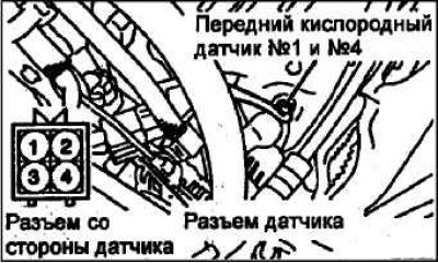
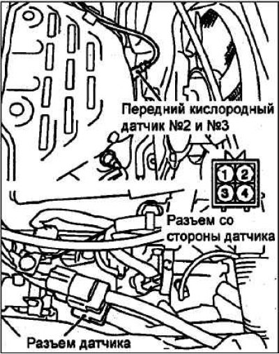
Disconnect the oxygen sensor connector and connect a special tool (test wire harness) to the connector on the sensor side.
Check that the circuit between terminal 3 and terminal 4 of the oxygen sensor connector is closed (resistance between terminals is 4.5–8.0 ohms at 20°C).
If the circuit is open, replace the oxygen sensor.
Warm up the engine to a coolant temperature of 80°C or higher.
Using alligator clip wires, connect terminal 3 of the oxygen sensor connector to the "+" terminal of the battery, and terminal 4 to the "–" terminal of the battery.
Warning! Be very careful when connecting the wires with crocodile clips to the battery terminals (do not reverse the polarity); incorrect wiring may damage the oxygen sensor.
Connect a digital (electronic) voltmeter to terminals 1 and 2. Periodically pressing the accelerator pedal, measure the output voltage of the oxygen sensor.
Nominal value
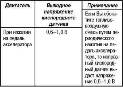
If the oxygen sensor is faulty, replace it.
Checking the rear oxygen sensor
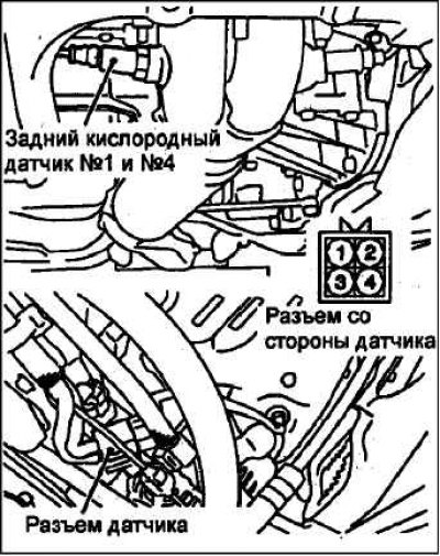
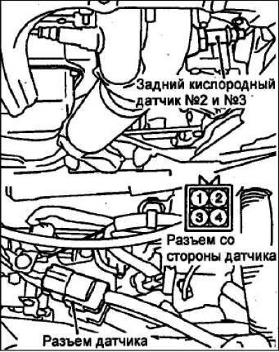
Disconnect the oxygen sensor connector and connect a special tool (test wire harness) to the sensor side.
Check that the circuit between terminals 3 and 4 of the oxygen sensor connector is closed (resistance between terminals is 11–18 ohms at 20°C).
If the circuit is open, replace the oxygen sensor.
Note: If the MUT-II does not display the standard values, although no fault was found during the above circuit check, replace the oxygen sensor (rear).
Change in resistance between injector terminals

Disconnect the connector from the injector.
Measure the resistance between the terminals.
Nominal value: 13–16 Ohm (at 20°C).
Connect the injector connector.
Checking the spray pattern of the injector and the tightness of the injector
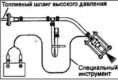
Relieve residual pressure from the fuel line according to the following procedure to prevent fuel splashing.
Remove the injector.
Assemble the special tool (injector test kit), adapter, pressure regulator and clamps as shown in the figure.
Apply battery voltage to terminal No.2 of the three-pin service connector of the fuel pump as shown in the figure, and turn on the fuel pump.
Activate the injector and check the quality of fuel atomization from the injector.
The condition of the injector is satisfactory if the injector produces a normal spray.

Disconnect the wires from the injector connector terminals and check the tightness (spray nozzle and shut-off needle) of the injector.
Norm: 1 drop or less per minute
Connect the wires from the battery terminals to the injector terminals without turning on the fuel pump. Then, after the fuel spray from the injector stops, disconnect the special tool, and set the injector to its original position.
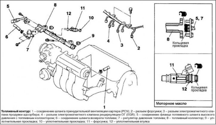
Checking the idle speed control servo drive (stepper motor); ISC) (check for the presence of the sound of the stepper motor operating)

Check that the coolant temperature is 20°C or below.
Note: It is also permissible to disconnect the coolant temperature sensor connector and connect another coolant temperature sensor with a temperature of 20°C to the connector on the wiring harness side. Disconnect and connect the electrical connector with the ignition off).
Check if the sound of the stepper motor operating can be heard after the ignition key has been turned to the "ON" position; without starting the engine).
If the sound of the stepper motor running is not heard, then check the stator winding circuits of the electric motor.
If no fault is found in the circuits, then there is probably a fault in the idle speed control servo (stepper motor) or in the electronic engine control unit.
Checking winding resistances
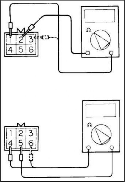
Disconnect the idle speed control connector and connect the special tool (test wire harness).
Measure the resistance between terminal 2 (white clamp) and terminal 1 (red clamp), and then to terminal 3 (blue clamp) on the idle speed control connector side.
Nominal value: 28–33 Ohm (at 20°C).
Measure the resistance between terminal 5 (green clamp) and terminal 6 (yellow clamp), and then to terminal 4 (black clamp) of the idle speed control connector.
Nominal value: 28–33 Ohm (at 20°C).