



Rotor
1. Check the excitation winding for continuity. Make sure that there is continuity between the contact rings. If the resistance is very low, this indicates a short circuit (Figure 7.3). If there is no continuity or a short circuit, the rotor should be replaced. Resistance: approximately 2-5 ohms.
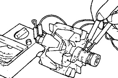
Figure 7.3. Checking the excitation winding for electrical conductivity
2. Check the excitation winding for a short circuit to the housing (Figure 7.4). Make sure that there is no electrical conductivity between the slip rings and the core. Otherwise, the rotor should be replaced.
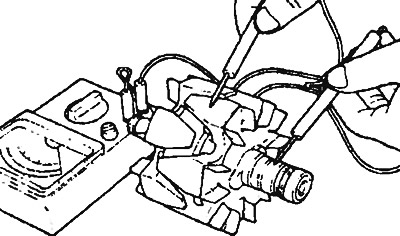
Figure 7.4. Checking the excitation winding for a short circuit to the housing
Stator
3. Check the electrical conductivity of the winding wires (Figure 7.5). If there is no electrical conductivity, the stator should be replaced.
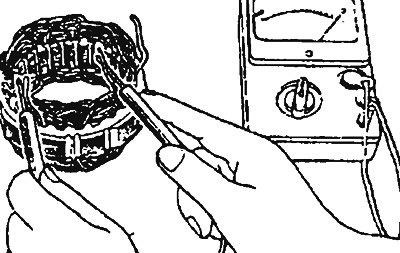
Figure 7.5. Checking the electrical conductivity of the stator winding
4. Check the contact of the stator winding with the housing (Figure 7.6). Make sure that there is no electrical conductivity between the winding wire and the core. If there is, the stator and rectifier should be replaced.
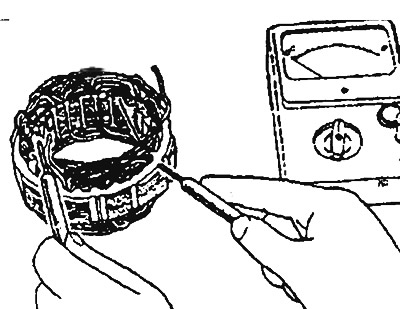
Figure 7.6. Checking the contact of the stator winding with the housing
Rectifier
1. Using an ohmmeter, check the continuity between the positive rectifier and the stator winding wire connection terminal. If continuity is present in both directions, the diode is short-circuited. In this case, the rectifier must be replaced (Figure 7.7).

Figure 7.7. Checking the positive rectifier
2. Using an ohmmeter, check the continuity between the negative rectifier and the stator winding wire connection terminal. If continuity is present in both directions, the diode is short-circuited. In this case, the rectifier must be replaced (Figure 7.8).
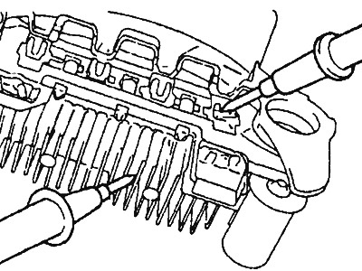
Figure 7.8. Testing the negative rectifier
(The material was copied from the website: www.MitsubishiMan.ru)
3. Using an ammeter, check the conductivity of each of the three diodes at both ends. If there is no conductivity in both directions, the diode being tested is short-circuited. In this case, the heat sink is changed (Figure 7.9).
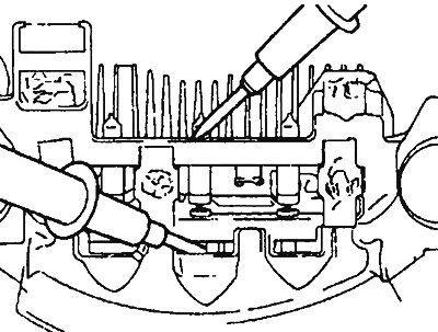
Figure 7.9. Testing a triple diode
4. Brushes that are worn beyond the permissible limit must be replaced (Figure 7.10).
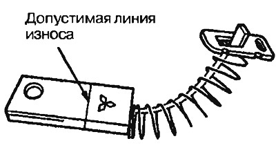
Figure 7.10. Generator brush
5. The connecting harnesses are unsoldered, the old brush with the spring is removed (Figure 7.11).
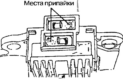
Figure 7.11. The connecting harnesses are unsoldered, the old brush with the spring is removed
6. The new brush is installed in the brush holder and then the wire is soldered (Figure 7.12).
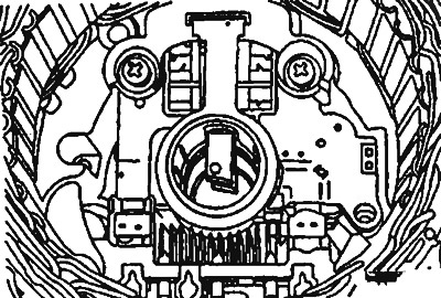
Figure 7.12. The new brush is installed in the brush holder and then the wire is soldered