



Contents: Removal ⤓ Installation ⤓
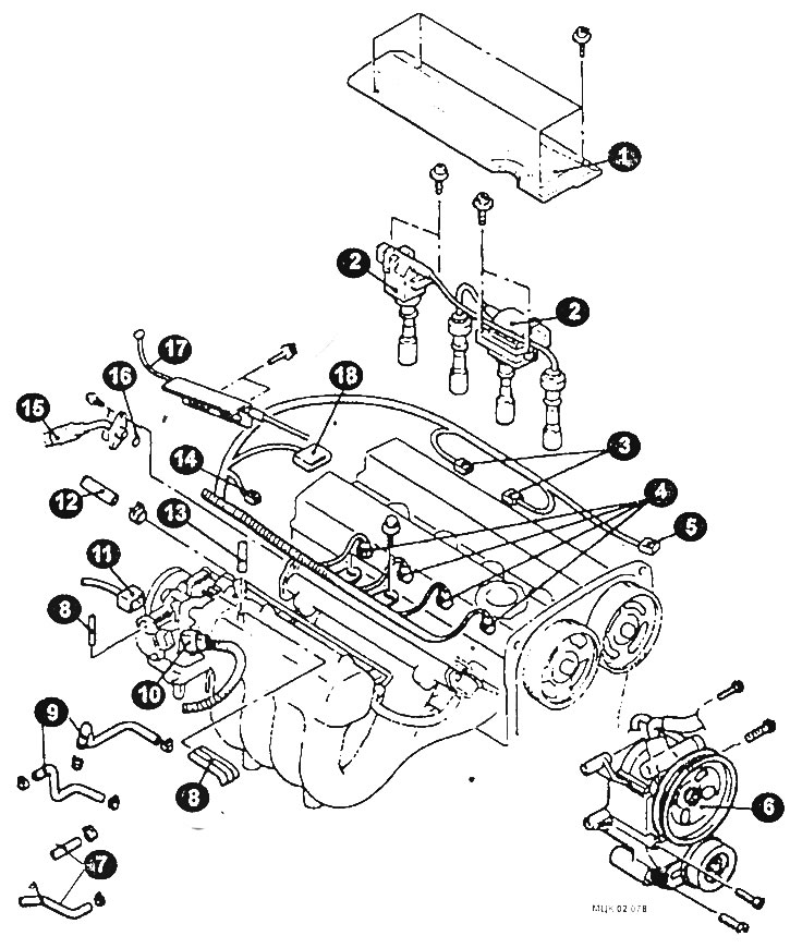
External engine components
1 - top cover; 2 - ignition coil; 3 - ignition coil connector; 4 - electrical connector of the injector; 5 - camshaft position sensor connector; 6 - Power steering pump; 7 - heater hoses; 8 - vacuum hoses; 9 - Cooling system hoses; 10 - throttle position sensor connector; 11 - idle speed controller connector; 12 - fuel return hose; 13 - brake booster hose; 14 - Oil pressure switch sensor connector; 15 - high pressure fuel hose connection; 16 - seal; 17 - gas pedal cable; 18 - ignition system sensor connector.
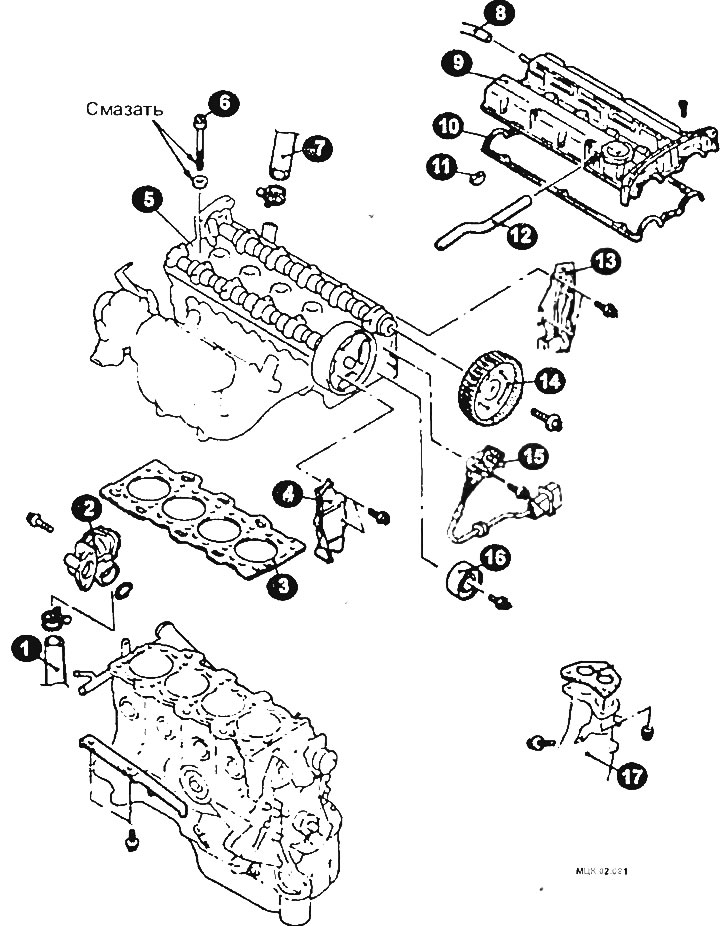
Cylinder head gasket mounting elements
1 - radiator hose; 2 - cooling system pipe; 3 - cylinder block column gasket to; 4 - rear cover of the timing belt; 5 - cylinder head; 6 - cylinder head mounting bolt; 7 - radiator hose; 8 - forced crankcase ventilation hose; 9 - cylinder head cover, 10 - gasket; 11 - semicircular insert; 12 - hose 4 of the engine ventilation system; 13 - rear cover of the sponge belt; 14 - camshaft gear for exhaust valves; 15 - camshaft position sensor; 16 - idler pulley; 17 - intake pipe of the exhaust gas system.
Removal
Disconnect the ground cable from the battery.
Relieve fuel pressure in the fuel system.
Drain the coolant from the engine cooling system into a suitable container.
Remove the air intake hose.
Remove the camshaft drive belt. Disconnect the gas pedal cable.
Remove the top cover.
Disconnect the ignition coil connectors.
Remove the ignition coils as an assembly.
Disconnect the electrical connectors for the throttle position sensor, idle speed control valve, oil pressure switch, ignition system sensor, injector and camshaft position sensor.
After loosening the clamp, disconnect the fuel return hose.
Disconnect the high pressure fuel hose and remove the sealing ring.
Disconnect the brake booster hose.
Disconnect the cooling system hoses.
Disconnect the heater hoses.
Remove the bracket and the power steering pump assembly together with the hoses connected to it.
Tie the removed power steering pump to the car body with wire.
Disconnect the radiator hose.
Remove the coolant supply pipe and thermostat housing assembly and gasket.
Disconnect the positive crankcase ventilation hose.
Remove the cylinder head cover and gasket.
Remove the semicircular plug.
Holding the camshaft with a wrench, unscrew the camshaft gear mounting bolts.
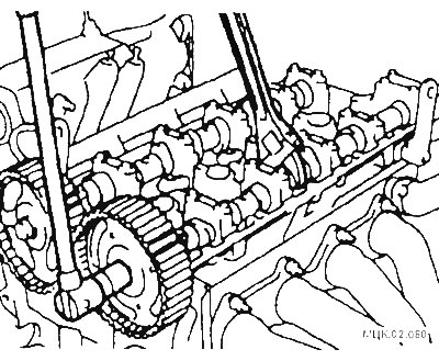
Remove the exhaust camshaft gear.
After unscrewing the bolt, remove the idler pulley.
After unscrewing the bolt, remove the camshaft position sensor.
After unscrewing the bolts, remove the rear cover of the camshaft drive belt.
Remove the exhaust pipe and gasket.
Gradually loosen the cylinder head mounting bolts in 3 steps in the sequence shown in the figure, and then remove the cylinder head assembly.
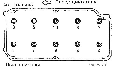
Sequence of unscrewing cylinder head bolts
Remove the cylinder head gasket.
Installation
Installation is carried out in reverse order, taking into account the following.
Clean the mating surfaces of the cylinder block and head gasket.
Check that all holes on the gasket and cylinder head match.
Check the length of the bolt rod, which should not be more than 96.4 mm. If this value increases, the bolt must be replaced.
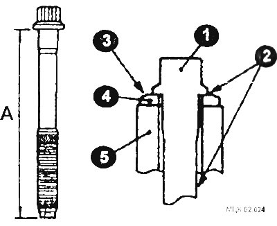
1 - bolt head; 2 - places of application of motor oil; 3 - chamfer; 4 - washer; 5 - cylinder head; A - 96.4 mm.
Install the bolt washer so that the chamfered surface of the washer is on top.
Before installation, lubricate the top surface of the washer and the bolt threads with a small amount of engine oil.
Tighten the cylinder head bolts in several steps in the sequence shown in the figure.
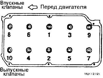
- Step 1: Tighten to 78 Nm
- Step II: Loosen all bolts completely in reverse order
- Step III: Tighten to 20 Nm
- IV step: apply paint marks on the bolt heads and cylinder head and turn 90°
- Step 5: Tighten another 90°. The marks on the bolts and cylinder head should be in line
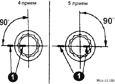
CAUTION: Always tighten the bolt to an angle exactly equal to 90°. Otherwise, the cylinder head mounting bolt may become loose. If the bolt was accidentally tightened to an angle greater than 90°, it must be completely loosened and all bolt tightening operations must be repeated.
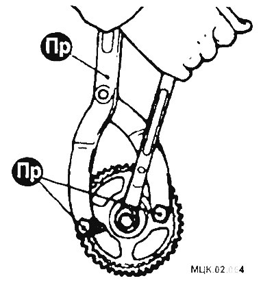
When installing the exhaust camshaft gear, secure the wheel from turning with a special device in the same way as when removing it, and tighten the gear mounting bolt to a torque of 38 Nm.
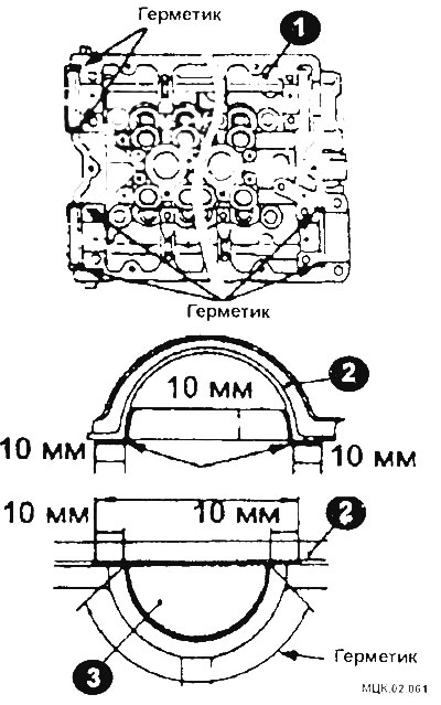
Before installing the cylinder head cover gasket, apply sealant to the areas indicated in the figure.
When installing the supply pipe (1) of the cooling system, loosen the supply pipe fastening bolt (arrow in the figure).
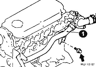
When installing the inlet pipe and thermostat assembly, apply layers of sealant to the mating surface of the inlet pipe.
Coat the coolant supply pipe gasket with soapy water and insert the thermostat housing into the coolant supply pipe.
Tighten the thermostat housing assembly mounting bolts and the cooling system supply pipe mounting bolt.
When installing the high pressure fuel hose, lubricate the sealing ring with a small amount of clean engine oil.
Slightly rotate the fuel hose flange and insert it into the fuel manifold. After installation, check that the hose rotates smoothly in the fuel manifold.