
English Русский
Български
Беларускі
Український
Српски
Hrvatski
Română
Polski
Slovenský
Magyar
Articles Bookmark Contacts Sitemap   
Company Audi Company Ford Company Hyundai Company Kia Company Mazda Company Mercedes-Benz Company Nissan
MitsubishiMan.ru


Home Colt Lancer Galant L200 Outlander Pajero Others
Carisma (1995-2004) Space Star (1998-2005)

Crankshaft seals — removal and installation (Mitsubishi Carisma)

  • Home
  • Mitsubishi
  • Carisma (1995-2004)
  • Power unit
  • Petrol engines 4G9
  • Crankshaft seals — removal and installation
0
Contents: Front crankshaft oil seal ⤓ Rear crankshaft oil seal ⤓

Front crankshaft oil seal


Removal


1. Remove the timing belt.

2. Remove the crankshaft V-belt pulley.
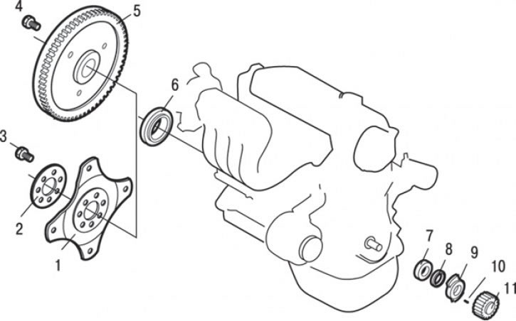


Fig. 3.34. Crankshaft oil seals: 1 – torque converter drive plate (ATP); 2 – adapter plate (AKP); 3 – bolt, 93–103 Nm; 4 – bolt, 93–103 Nm; 5 – flywheel assembly (automatic transmission); 6 – rear crankshaft oil seal; 7 – front crankshaft oil seal; 8 – Crankshaft spacer ring (DOHC); 9 – sensor rotor (DOHC); 10 – key; 11 – crankshaft pulley


3. Remove pulley 11 (Fig. 3.34) of the crankshaft toothed belt and key 10.

4. Remove the sensor rotor and spacer ring 8 of the crankshaft (DOHC).

5. Drill two small holes in the front crankshaft oil seal, located at diametrically opposite ends of the oil seal. Screw two self-tapping screws into the drilled holes in the oil seal and use pliers to pull out oil seal 7 by the screw heads.

6. Clean the oil seal seat.

Installation


Installation is carried out in the reverse order of removal, taking into account the following.

1. Lubricate the entire working edge of the oil seal with a small amount of engine oil.
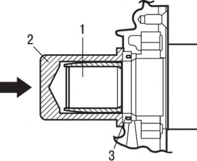


Fig. 3.35. Using mandrels to install the front crankshaft oil seal: 1 – crankshaft; 2 – mandrel MD998717; 3 – oil seal


2. Install the seal by lightly tapping the mandrel until it is flush with the seal body (Fig. 3.35).

3. Remove all traces of engine oil and install the crankshaft pulley.

Rear crankshaft oil seal


Removal


1. Remove the crankshaft position sensor.

2. Remove the engine oil pan.

3. Remove the gearbox assembly.

4. Remove the clutch housing and clutch driven disc.

5. Secure the flywheel or torque converter drive plate from turning by installing a special tool on the flywheel ring gear, unscrew the mounting bolts and remove the flywheel or torque converter drive plate and adapter plate 2 (see Fig. 3.34).

6. Drill two small holes in the rear crankshaft oil seal, located at diametrically opposite ends of the oil seal. Screw two self-tapping screws into the drilled holes in the oil seal and use pliers to pull out oil seal 6 by the screw heads.

7. Clean the oil seal seat.

Installation


Installation is carried out in the reverse order of removal, taking into account the following.

1. Lubricate the entire working edge of the oil seal with a small amount of engine oil.
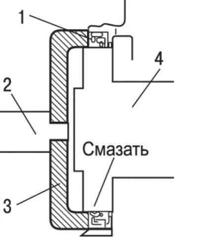


Fig. 3.36. Using mandrels to install the rear crankshaft oil seal: 1 – rear crankshaft oil seal; 2 – mandrel MD990938; 3 – mandrel MD998776; 4 – crankshaft


2. Install the seal by pressing it so that the end surface is located at the level of the chamfer of the seal housing (Fig. 3.36).

3. Before installation, clean the bolts, threaded holes in the crankshaft and flywheel (manual transmission) or torque converter drive plate (automatic transmission) from oil, sealant and other contaminants.
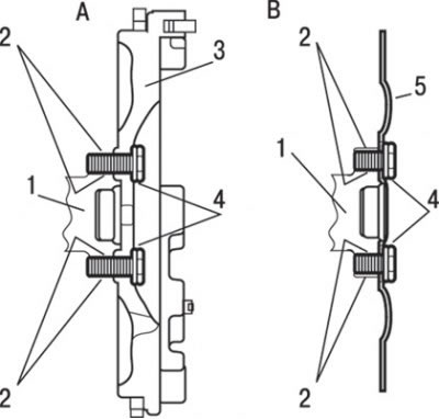


Fig. 3.37. Places to apply sealant and grease when installing the rear crankshaft oil seal: A – manual transmission; B – automatic transmission; 1 – crankshaft; 2 – places of application of sealant ЗМ STUD Locking 4170 or similar; 3 – flywheel; 4 – places where engine oil is applied under the bolt washer; 5 – drive plate


4. Lubricate the contact surfaces of the flywheel mounting bolts (manual transmission) or the torque converter drive plate (automatic transmission) with oil (Fig. 3.37).

5. Apply engine oil to the flywheel holes.

6. Apply sealant ЗМ STUD Locking 4170 or similar to the threads of the holes for the mounting bolts (see Fig. 3.37).

7. Using the special tool as for removal, secure the flywheel or torque converter drive plate and tighten the mounting bolts to 93–103 N·m.
This article is available at: russian, bulgarian, belarusian, ukrainian, serbian, croatian, romanian, polish, slovak, hungarian
This article was reviewed by: Dmitry Vasiliev
Share with friends:
◀ Previous
Carisma: Petrol engines 4G9
Next ▶

DOHC Engine Oil Pan
SOHC Engine Oil Pan
Camshafts and camshaft seals for GDI models
Camshafts and camshaft seals for DOHC engines
SOHC Engine Camshaft and Camshaft Seal
SOHC Engine Cylinder Head Gasket
DOHC Engine Cylinder Head Gasket
Timing belt drive the SOHC engine
Timing belt drive the DOHC engine
Removal and installation of the SOHC engine assembly
Similar materials for other Mitsubishi models

➤ Crankshaft Seals (SOHC, 16 valves) Mitsubishi Colt 4 and 5 (1991-2003)
➤ Checking the rubber seals of the drive shafts Mitsubishi Lancer 3 and 5 (1984-1992)
➤ Removal and installation the crankshaft vibration damper Mitsubishi Galant 6 and 7 (1987-1998)
➤ Installing the crankshaft seals and front upper cover Mitsubishi L200 4 (2005-2014, diesel)
➤ Removal and installation front and rear crankshaft oil… Mitsubishi Outlander 1 (2003-2008)
➤ Removal the crankshaft seals Mitsubishi Pajero 4 (2006-2021)
Link in different formats to this article
Comments and feedback from visitors
No comments yet


Add up two numbers 40 + 26


Carisma (1995-2004) 
  • General information
  • User manual
  • Maintenance
  • Power unit
  • Petrol engines 4G9
  • Diesel engines FBQT
  • Diesel engines F9Q
  • Cooling system
  • Injection system (MPI)
  • Injection system (GDI)
  • Engine electrical equipment
  • Transmission
  • Clutch
  • Mechanical gearbox
  • Automatic gearbox
  • Chassis and running gear
  • Steering
  • Brake system
  • Front suspension and shafts
  • Rear suspension
  • Body and interior
  • Exterior (external elements)
  • Interior (internal elements)
  • Doors, locks and windows
  • Air conditioner
  • Electrical equipment
  • Equipment and devices
  • Headlights and lighting
  • Electrical circuits
Space Star (1998-2005) 
  • General information
  • User manual
  • Maintenance
  • Power unit
  • Petrol engines 4G9
  • Petrol engines 4G1
  • Diesel engines F9Q1
  • Cooling system
  • Fuel injection system GDI
  • Fuel injection system MPI
  • Diesel supply system F9Q1
  • Ignition system
  • Diesel preheating
  • Transmission
  • Clutch
  • Mechanical gearbox
  • Automatic gearbox
  • Chassis and running gear
  • Suspension and drive shafts
  • Brake system
  • Steering
  • Body and interior
  • Exterior (external elements)
  • Interior (internal elements)
  • Doors, locks and windows
  • Heating and air conditioning
  • Electrical equipment
  • Power devices
  • Equipment and devices
MitsubishiMan.ru © 2018–2026 • Mobile version • Articles about Mitsubishi • Contacts • Sitemap: EN BG BY UA RS HR RO PL SK HU • Site search • Bookmark
Colt 2 and 3 (1983-1993) · Colt 4 and 5 (1991-2003) · Colt 5 (1995-2003) · Lancer 3 and 5 (1984-1992) · Lancer 9 (2000-2007) · Galant 5 (1983-1989) · Galant 6 and 7 (1987-1998) · L200 4 (2005-2014) · Outlander 1 (2003-2008) · Pajero 1 and 2 (1982-1999) · Pajero 4 (2006-2021) · Carisma (1995-2004) · Space Star (1998-2005) ·
This resource sets cookies 🍪 to avoid bothering you with repeated data entry.