
Tubes of the injection system and injection pump
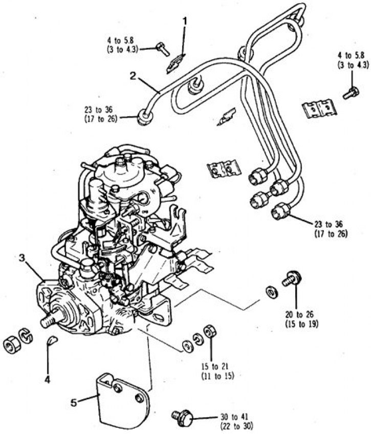
1. Bracket; 2. Tube; 3. Flange; 4. Key; 5. Bracket
Attention! To perform the procedure, you will need an indicator with a division value of 0.001 mm with a special extension MD998384.
Installation
1. Set the piston of the 1st cylinder to the TDC of the compression stroke.
2. Loosen the injection fittings on the pump.
3. Loosen the bolts and nuts securing the pump to the engine.
4. Check the protrusion of the indicator extension rod, which should be 10 mm, adjust if necessary by turning the nut.
5. Remove the plug from the pump head and screw in tool MD998384.
6. Carefully turn the crankshaft counterclockwise, 30°to TDC. Label (excavation) should be facing approximately 11 o'clock.
7. Set the indicator scale to 0 and turn the crankshaft slightly in both directions, while the indicator needle should be stationary. Otherwise, repeat the installation of the crankshaft 30°to TDC, achieving the immobility of the arrow.
8. Turn the crankshaft clockwise, aligning the mark with the division 5°after TDC - in this position of the crankshaft, the indicator reading should be 0.997–1.003 mm.
9. If the indicator reading differs from the specified one, then moving the pump housing, set the desired indicator readings, then tighten the nuts and bolts of the pump.
10. Repeat the installation procedure and check the injection time several times - each time the crankshaft is set to 30°before TDC and 5°after TDC, the indicator reading should be 0.997–1.003 mm.
11. Replace the copper gasket and tighten the plug to 8 Nm.
12. Tighten bolts and bleed air.