



Contents: Checking the ABS hydraulic unit…⤓ Table. Checking the ABS electronic…⤓ Checking the voltage of the wheel…⤓ Table. ABS electronic control unit…⤓ Checking the Wheel Speed Sensor…⤓ Table. Voltage at the terminals of…⤓
Checking the ABS hydraulic unit using a tester
1. Raise the vehicle with a jack and install safety stands in specially designated places under it, or install the wheels being tested on the drums of the brake test stand.
Attention:
- The surfaces of the brake tester drum and the vehicle wheel tires must be dry.
- When testing the front brakes, apply the parking brake on the vehicle.
- When testing the rear brakes, block the front wheels.
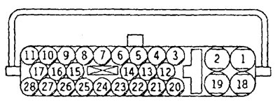
ABS electronic control unit wiring harness connector.
Table. Checking the ABS electronic control unit wiring harness connector.
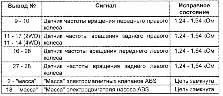
2. Release the parking brake lever and check the resistance force to rotation (resistance torque) on each wheel.
Note: When using a brake tester, record the measured drag force values at each wheel.
3. Turn the ignition key to the "OFF" position and connect the tester to the diagnostic connector.
Caution: Before connecting (or disconnecting) the tester, turn the ignition switch to the "OFF" position.
4. After making sure that the automatic transmission selector is in the "N" position, start the engine.
5. Using the "ACTUATOR TEST" function, forcefully activate the brake drive for each wheel.
Note:
- During the test, the ABS indicator light will be on and the ABS control will be disabled.
- Checking the actuators is not possible if the ABS system emergency mode is activated.
6. Turn the wheel by hand and check the change in braking force when the brake pedal is pressed (the pressure force is sufficient to lock the wheel).
Note: When using a brake tester, press the brake pedal until the braking force reaches the specified values, then check whether the braking force decreases when the ABS hydraulic unit components are forced to engage to the values measured in item 2.
Nominal value:
- Front wheel - 785 - 981 N
- Rear wheel - 588 - 784 N
7. Analysis of the inspection results.
a) In normal conditions, the braking force should be released 3 seconds after the wheel locks (see figure).
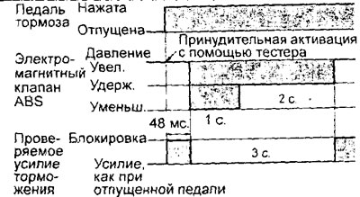
b) When checking according to points 1-2: if the wheel does not lock when the brake pedal is pressed, then either the brake system tubes (point 1) or the hydraulic unit channels (point 2) are clogged.
c) When checking items No.03-No. 4: if the braking force does not weaken, then either the brake pipes are not connected correctly to the hydraulic unit, or the ABS electromagnetic valves inside the hydraulic unit are not working correctly.
8. After completing the test, turn the ignition key to the "OFF" position and disconnect the tester.
Checking the voltage of the wheel speed sensor signal
1. Raise the vehicle using a lift (hang the wheels) and release the parking brake.
2. Disconnect the connector from the ABS electronic control unit and connect the test wiring harness to it.
3. While rotating the wheel at approximately 0.5 - 1.0 revolutions per second, measure the signal output voltage at the connector on the wiring harness side using a multimeter or oscilloscope (see the table "ABS ECU Pins for Sensor Testing").
Table. ABS electronic control unit pins for checking sensors.

Output voltage when measured:
- multimeter - 42 mV or more
- oscilloscope (signal amplitude) - 120 mV or more
5. If the output voltage is less than the specified values, the causes of the malfunction may be:
- a) Wheel speed sensor.
- b) Excessive clearance between the pole piece of the wheel speed sensor and the rotor of the speed sensor.
Checking the Wheel Speed Sensor Signal Waveform with an Oscilloscope
Verification procedure
Set the transfer case lever to the "2H" position. Start the engine and rotate the rear wheels, engaging first gear. Rotate the front wheels manually, maintaining a constant rotation speed.
Note:
- - Before connecting the oscilloscope, check for contact in the wires and the sensor connector.
- - The signal waveform test can also be performed directly on a moving vehicle.
- - At low speed, the output voltage will be low. Accordingly, it will increase with increasing speed.
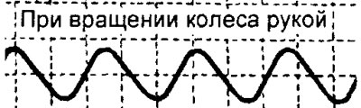
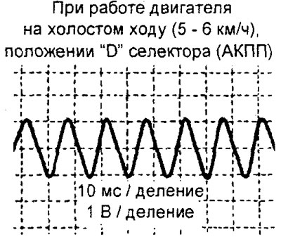
Parameters to pay attention to when observing a signal
1. If the oscillation amplitude is very small or zero, then either the wheel speed sensor is faulty (replace the sensor) or the gap between the rotor and the pole piece is not normal (adjust the gap).
2. If the deviation in vibration amplitude is too large (minimum: an amplitude of 100 mV or more is not a malfunction), then either large eccentricity or significant runout of the wheel hub is present (replace the wheel hub).
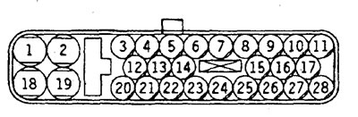
ABS electronic control unit connector.
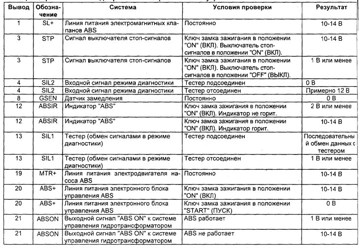
Table. Voltage at the terminals of the ABS electronic control unit connector.
(The original can be found on the website MitsubishiMan)
3. If there is interference or distortion of the signal form, then it is possible:
- a) Open circuit in the sensor (replace the sensor).
- b) Broken wiring (fix or replace).
- c) Incorrect installation of the sensor (install the sensor correctly).
- d) Damage or breakage of the sensor rotor tooth (replace the rotor).
Note: Since the wheel speed sensor wiring moves according to the front or rear suspension travel, there may be a disconnection in the circuit (broken wiring) when driving on gravel roads, but the wheel speed sensor will function normally when driving on normal roads. Therefore, when measuring the output waveform (signal voltage) of the sensor, simulate similar road conditions (uneven road) by shaking the sensor wiring.