



Removal and installation
− Before starting to remove parts, remove the lower part of the center console and, if necessary, the front driver's seat (see chapter "Body").
− Removal is carried out in the order of numbers indicated in the figures "Removing the parking brake components (models with rear disc brakes) and the parking brake drive cable".
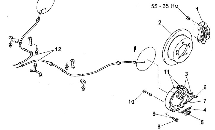
Removal the parking brake components (models with rear disc brakes) and the parking brake cable. 1 - rear brake caliper assembly; 2 - rear brake disc; 3 - brake shoe return springs; 4 - regulator spring; 5 - brake clearance adjuster; 6 - brake pad spacer plate; 7 - spacer plate spring; 8 - shoe support pin cap; 9 - pad support pin spring; 10 - shoe support pin; 11 - brake pads (with linings); 12 - parking brake drive cable.
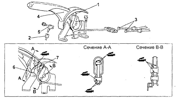
Removal the parking brake lever. 1 - adjusting nut; 2 - parking brake indicator switch connector; 3 - connection of parking brake drive cables in assembly; 4 - parking brake lever assembly; 5 - Parking brake indicator switch.
- (Models with rear disc brakes) When removing parts, pay attention to the following operations:
1. Removing the caliper assembly.
The removed brake caliper must be suspended using wire.
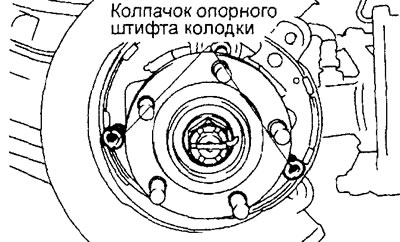
2. Removing the brake shoe support pin cap.
Spread the parking brake shoes and remove the shoe support pin caps.
- Installation is carried out in the reverse order of removal.
- When installing parts, pay attention to the following operations:
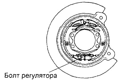
1. Installing the brake clearance adjuster.
Caution: Install the adjuster so that the adjuster bolt on the left rear wheel faces the front of the vehicle and the adjuster bolt on the right rear wheel faces the rear of the vehicle.
2. Installing the brake shoe return springs.
Install the return springs as shown in the figure.
Note: The load characteristics of the respective shoe return springs are different. The spring characteristic can be determined by the presence of the identification color mark shown in the figure.
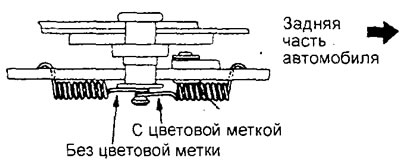
Note: The figure shows the spring arrangement for the left wheel. For the right wheel, the spring arrangement will be symmetrical.
- After completing the installation of the parts, perform the following operations:
- a) Adjust the stroke of the parking brake lever
- b) Install the lower part of the center console and the front driver's seat (see chapter "Body").
Checking the wear of the brake shoe and drum of the parking brake (models with rear disc brakes)
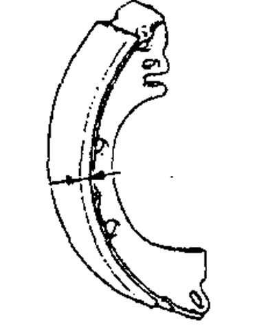
1. Measure the friction lining thickness of the parking brake shoe in several places.
Nominal value - 2.8 mm
The maximum permissible value is 1.0 mm
Caution: If the lining thickness is equal to or less than the maximum permissible value, replace the parking brake pads.
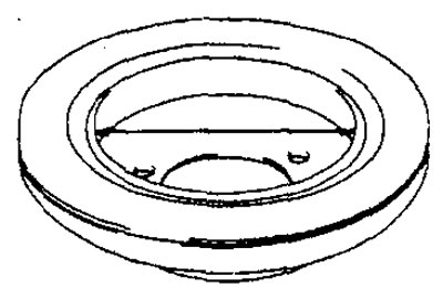
2. Measure the parking brake drum diameter (inner diameter of the brake disc) in several places.
Nominal value - 168 mm
The maximum permissible value is 169 mm
Caution: If the parking brake drum diameter is equal to or greater than the maximum permissible value, replace the rear brake disc.
Original version of the article on the website MitsubishiMan.ru