
Removal and installation
− Drain the brake fluid before removing parts.
− Removal of parts is carried out in the order of numbers indicated in the figure "Removing the front disc brake".
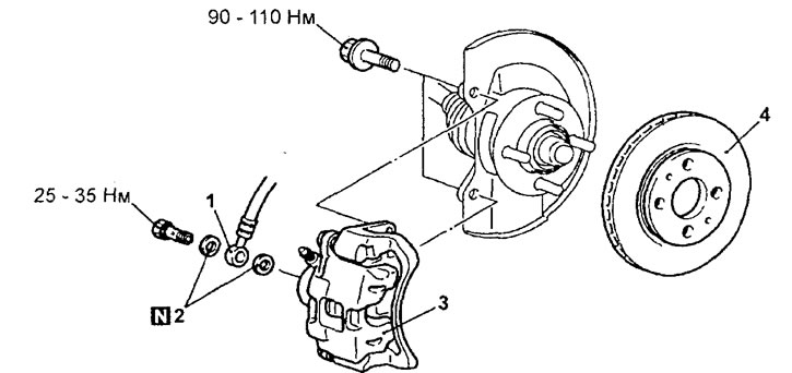
Disc brakes. 1 - brake hose connection, 2 - gasket, 3 - disc brake caliper assembly, 4 - brake disc.
− Installation of parts is carried out in the reverse order of removal.
− When installing the parts, pay attention to the operation of measuring the wheel hub rotation resistance when installing the front disc brake caliper assembly.
A) Remove the drive shaft (see chapter "Front drive shafts").
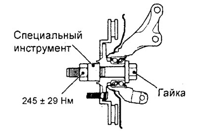
b) Install the special tool in the hub as shown in the figure and tighten it.
Tightening torque - 216 - 274 Nm
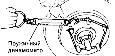
3. Measure the resistance to rotation "A" wheel hub in the forward direction when the brake pads are not installed.
4. Start the engine and depress the brake pedal hard 2-3 times.
5. Stop the engine.
6. Rotate the brake disc in the forward direction about 10 turns.
7. Using a spring dynamometer, measure the resistance "IN" rotation of the wheel hub in the forward direction.
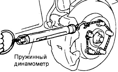
8. Calculate the value of the force of resistance to rotation of the wheel hub with disc brake installed (difference between values "A" And "IN").
Rated value - no more than 78 Nm
9. If the force of resistance to rotation of the wheel hub exceeds the nominal value, then disassemble the caliper. Check for corrosion or wear on the piston o-ring and piston, and check that the caliper slides easily over the guide pins.
− After completing the installation of the parts, perform the following operations:
- A) Refill with brake fluid.
- b) Remove air from the brake hydraulic drive.
Disassembly and assembly
− Removal of parts is carried out in the order of numbers indicated in the figure "Disassembly of the front disc brake".
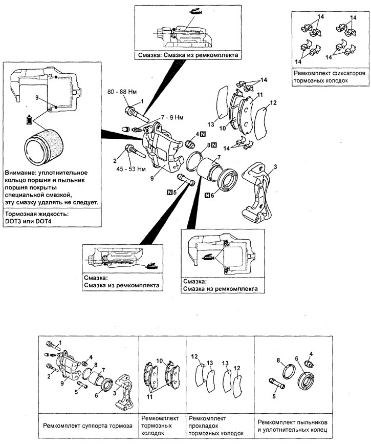
Disassembly of the front disc brake (except models with 4G63T engine). 1 - locking pin, 2 - guide pin, 3 - bushing, 4 - caliper bracket (complete with pads and clamps), 5 - pin boot, 6 - piston boot clamp, 7 - piston boot, 8 - piston, 9 - piston o-ring, 10 - caliper, 11 - brake shoe and wear indicator assembly, 12 - brake shoe assembly, 13 - inner gasket, 14 - outer gasket, 15 - retainer.
− When removing parts, pay attention to the following operations:
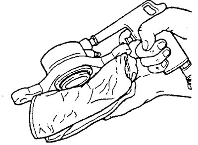
- 1. Removing the piston and its anther.
Wrap the caliper with a cloth. Apply compressed air to the brake hose opening to remove the piston and piston boot.
Attention: when removing the piston, be careful, supply compressed air gradually.
- 2. Removing the piston sealing ring.
A) Remove the piston o-ring with your finger.
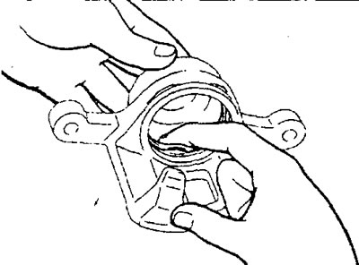
Attention: to prevent damage to the inner surface of the working brake cylinder, do not use a flat screwdriver or other tool to remove the ring.
b) Wash piston and cylinder surfaces with trichlorethylene, alcohol, or recommended brake fluid.
Brake Fluid Type - SAE J1703 or FMVSS 116 DOT3 or DOT4
Installation of parts is carried out in the reverse order of removal.
Check after disassembly
1. Check for rust, wear and damage to the brake cylinder mirror.
2. Check the absence of rust, damage and wear on the surface of the piston of the brake cylinder.
3. Check the caliper and bushings for wear.
4. Check for damage or oiling on the brake pad linings, as well as for damage to the metal bases of the pads.
Checking brake pad wear
Measure the thickness of the brake pad lining at the narrowest and most worn point. Replace the brake pad assemblies if the lining thickness is less than the limit.
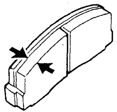
Nominal value - 10.0 mm
Maximum allowable - value 2.0 mm
Attention:
- - If the lining thickness of any pad is less than the maximum allowable value, then replace the brake pads as a set, in addition, simultaneously replace the brake pads on the opposite wheel of this axle.
- - If there is a noticeable difference in the thickness of the brake pads on the left and right sides, then check the condition of the sliding parts of the caliper.