



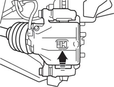
Fig. 14.7. Checking the thickness of the brake pad linings through a special hole in the caliper body
1. Check the thickness of the brake pad linings through a special hole in the caliper body (Fig. 14.7).
Caution: If the brake pad lining thickness decreases below the maximum permissible value, replace all disc brake pads on both wheels.
Caution! If there is a significant difference between the thickness of the right and left brake shoe linings, check the operation of the working brake cylinder piston and guide pins.
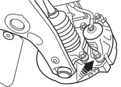
Fig. 14.8. Location (arrow) of the lower guide pin on the front brake caliper
2. Unscrew and remove the lower guide pin (Fig. 14.8). Raise the caliper assembly and secure it with wire.
Caution! Do not wipe off the special grease from the surface of the guide pin and do not allow it to become dirty.
(The original can be found on the website: www.MitsubishiMan.ru)
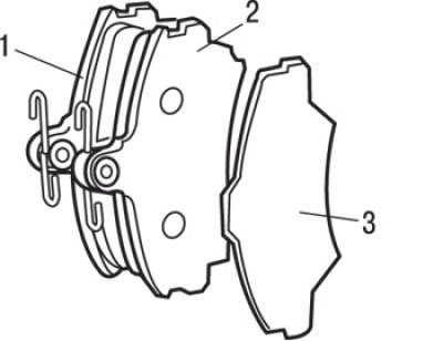
Fig. 14.9. Front brake pads: 1 – brake shoe with wear indicator assembly; 2 – outer brake shoe; 3 – outer gasket
3. Remove the brake pads with wear indicator assembly and outer lining one by one (Fig. 14.9).
4. To measure the rotating resistance force after installing new brake pads, measure the rotating resistance of the wheel hub bearing without brake pads.
5. Install the brake pads and caliper assembly, then measure the rotating resistance force.