
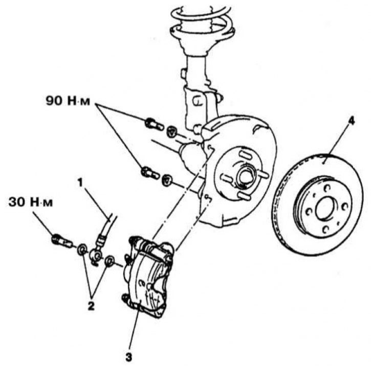
The design of the front wheel disc brake of Mirage models (for Galant models up to 1993 vol. there is a similar picture)
1 - Brake hose; 2 - Sealing washers; 3 - Caliper; 4 - Brake disc
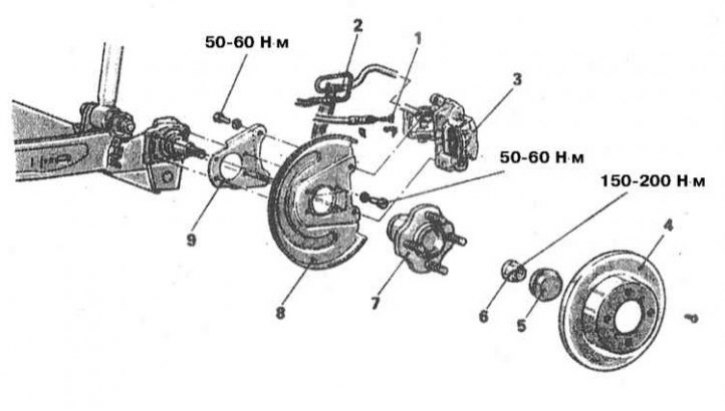
Rear wheel disc brake design for Mirage models (for Galant models up to 1993 vol. there is a similar picture)
1 - Parking brake cable; 2 - Brake hose; 3 - Assembling the caliper; 4 - Brake disc; 5 - Hub nut cover; 6 - Hub nut; 7 - Hub assembly; 8 - Brake shield; 9 - Bracket
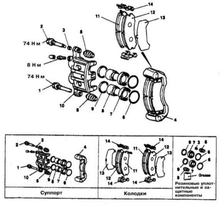
The design of the two-cylinder disc brake mechanism of the front wheel of the Diamante models
1 - Guide pin; 2 - Blocking finger; 3 - Bushing; 4 - Anchor bracket; 5 - Protective cover; 6 - Retaining ring; 7 - Anther; 8 - Piston; 9 - Cuff; 10 - Caliper; 11 - Assembling the pads with the wear indicator of the friction lining; 12 - Brake shoe; 13 - Outer shim; 14 - Spring retainer
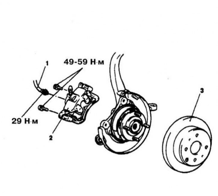
The design of the disc brake mechanism of the rear wheel of Galant models 1994÷1995. issue
1 - Brake hose; 2 - Assembling the caliper; 3 - Brake disc
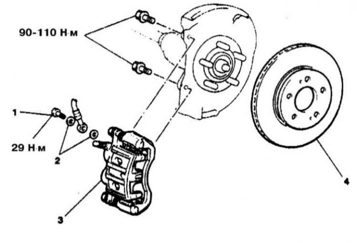
The design of the disc brake mechanism of the front wheel of Galant models since 1996, no.
1 - Hollow bolt of the union connection of the brake hose; 2 - Sealing washers; 3 - Assembling the caliper; 4 - Brake disc
Warning! The brake pads must be replaced on both front/rear brakes at the same time. Remember that the dust generated during the operation of the brake mechanisms may contain asbestos, which is extremely harmful to human health. Never blow off dust with compressed air or inhale it - wear a protective mask or respirator when servicing mechanisms. Never use gasoline or petroleum-based solvents to clean brake system components - use only branded cleaners or methyl alcohol!
Mirage and Galant models through 1993 issue.
Front wheel brakes
Removing
1. The design of the front wheel disc brake mechanism for the Mirage and Galant models up to 1993, no. shown in the illustration.
2. Pump out some of the fluid from the GTZ reservoir. The reservoir should be approximately half empty to provide enough volume to raise the level when the pads are released.
3. Loosen the front wheel nuts. Jack up the front of the vehicle and place it on jack stands, set the parking brake/chock the rear wheels.
4. Remove the caliper guide pins and lift the caliper assembly off the brake anchor. Tie up the caliper in the raised position with a wire, preventing it from hanging on the brake hose.
Note. On some models, the caliper can be fixed in the raised position by removing only one of the guide pins, while the second one will play the role of a rotary axis.
5. Remove the brake pads with spring clips and shims - try to remember the order of installation of the components.
6. In order to fix the brake disc on the hub assembly, screw a pair of wheel nuts onto the studs and tighten them loosely.
Installation
1. Using a large clamp, press the caliper piston into the cylinder (on two-cylinder calipers, both pistons must be sunk).
2. Lubricate the sliding bearing surfaces of the brake mechanism and install the replacement brake shoes, placing the shims and spring clips in the correct order. Lower the caliper onto the anchor bracket - try not to pinch the protective cover, make sure that the brake hose is not twisted.
3. Lubricate, reinstall and tighten guide and locking pins.
4. Install the wheel and lower the vehicle to the ground.
5. Check the efficiency of the brake system - before starting sea trials, depress the foot brake pedal several times in order to shrink the components and raise the pressure in the hydraulic path.
Rear wheel brakes
Removing
1. The design of the disc brakes of the rear wheels on the Mirage and Galant models for 1993, no. shown in the illustration.
2. Pump out approximately 2/3 of the brake fluid from the GTZ reservoir - when the piston is pressed, the fluid level may begin to be forced out of the reservoir.
3. Jack up the car and put it on stands.
4. Remove the appropriate rear wheel.
5. Release the parking brake.
6. Disconnect the parking brake cable from the brake assembly.
7. Remove lower guide pin, lift caliper assembly up and tie in position.
8. Remove the outer shim, brake pads and spring clips - try to remember the installation position of the components.
9. In order to fix the brake disc on the hub assembly, screw a pair of wheel nuts onto the studs and tighten them loosely.
Installation
1. Rotate the caliper clockwise using special tool No. MB9f52, push it inside your cylinder.
2. Lubricate the sliding bearing surfaces of the brake mechanism and install the replacement brake shoes, placing the shims and spring clips in the correct order.
3. Lower the caliper onto the anchor bracket - try not to pinch the protective cover, make sure that the brake hose is not twisted.
4. Lubricate, reinstall and tighten lower guide pin.
5. Install the wheel and lower the vehicle to the ground.
6. Check the efficiency of the brake system - before starting sea trials, depress the foot brake pedal several times in order to shrink the components and raise the pressure in the hydraulic path.
Models Diamante and Galant since 1994 vol.
Brakes front and rear wheels
Note. Due to the fact that on these models the rear wheel disc brakes are not equipped with a parking brake drive, they do not differ in design from the front wheels and are considered together.
Removing
1. The design of disc brakes on Diamante and Galant models since 1994 vol. shown in the illustrations.
2. Pump out approximately 2/3 of the brake fluid from the GTZ reservoir - when the piston is pressed, the fluid level may begin to be forced out of the reservoir.
3. Jack up the car and put it on stands.
4. Remove the relevant wheel.
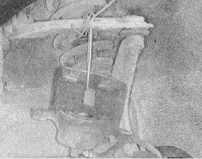
5. Remove the guide and blocking pins, then remove the caliper from the anchor bracket and tie it with wire, avoiding tension on the flexible brake hose.
Note. On some models, the caliper can be locked in the raised position by leaving it in place and using the top pin as a pivot point.
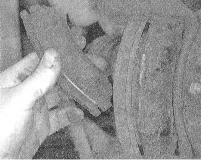
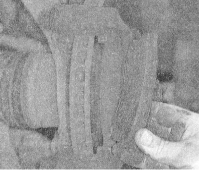
6. Remove the brake pads with spring clips and shims - try to remember the order of installation of the components.
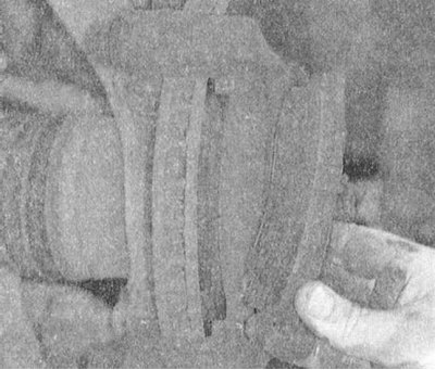 |  |
7. In order to fix the brake disc on the hub assembly, screw a pair of wheel nuts onto the studs and tighten them loosely.
Installation
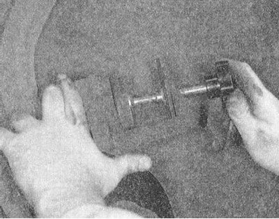
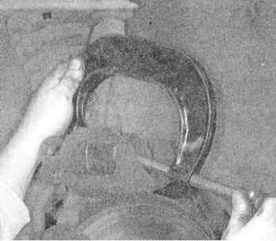
1. Using a special tool or a large clamp, press the caliper piston into the cylinder.
 |  |
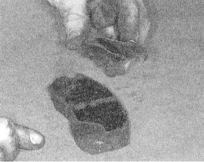 |
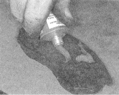
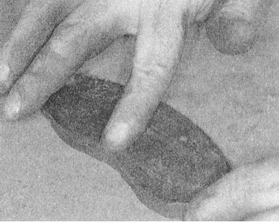
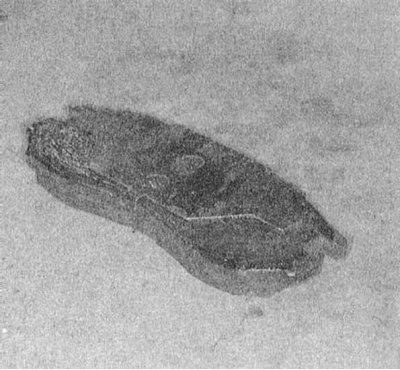
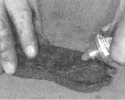
2. Lubricate the sliding bearing surfaces of the brake mechanism and install the replacement brake shoes, placing the shims and spring clips in the correct order. Lower the caliper onto the anchor bracket - try not to pinch the protective cover, make sure that the brake hose is not twisted.
 |  |
 |  |
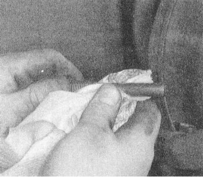
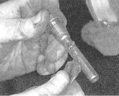
3. Lubricate, reinstall and tighten guide and locking pins. The tightening force for the guide and locking pins is 75 Nm for the front brakes and 27 Nm for the rear.
 |  |
4. Install the wheel and lower the vehicle to the ground.
5. Check the efficiency of the brake system - before starting sea trials, depress the foot brake pedal several times in order to shrink the components and raise the pressure in the hydraulic path.