
English Русский
Български
Беларускі
Український
Српски
Hrvatski
Română
Polski
Slovenský
Magyar
Articles Bookmark Contacts Sitemap   
Company Audi Company Ford Company Hyundai Company Kia Company Mazda Company Mercedes-Benz Company Nissan
MitsubishiMan.ru


Home Colt Lancer Galant L200 Outlander Pajero Others
Galant 6 and 7 (1987-1998) Galant 5 (1983-1989, petrol)

Removal and installation brake lines (Mitsubishi Galant 6)

  • Home
  • Galant
  • 6 (1987-1998)
  • Chassis and running gear
  • Brake system
  • Removal and installation brake lines
0
Contents: Rules for servicing hydraulic lines ⤓ Removal ⤓ Installation ⤓
Attention! Remember that the brake fluid drained from the system cannot be reused!


Rules for servicing hydraulic lines


1. The condition of metal and rubber brake lines should be checked on a regular basis in accordance with the vehicle's routine maintenance schedule (see Chapter Settings and ongoing maintenance). Carefully inspect all brake lines for mechanical damage and signs of developing leaks. Deformation of tubes can lead to a violation of their passability, which in this case is fraught with a violation of the efficiency of the brake system (up to a complete failure of the corresponding circuit). Rubber hoses should be checked for cracks, cuts, abrasions, swelling and other signs of destruction of protective fittings.
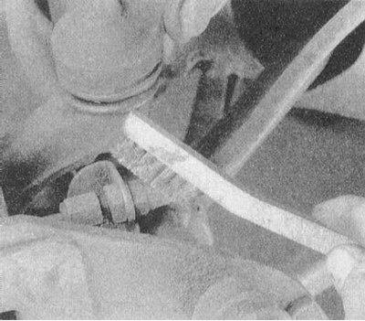


2. When disconnecting brake lines, pay special attention to maintaining cleanliness - before disconnecting, carefully clean the surface of the nipple connectors (use a brush and special cleaning agents). Immediately after disconnecting the lines, plug their open ends to prevent dirt and moisture from getting into the tract.


3. Before installation, replaceable sections should be washed with clean brake fluid.

Removal


1. Disconnect the negative cable from the battery.

Warning! If the car stereo system is equipped with a security code, make sure you have the correct combination to activate the audio system before disconnecting the battery!


2. Jack up the car and place it on supports.

3. To gain access to the brake line requiring service, remove the relevant wheel.

4. Carefully (using a special cleaner) wipe the nipple connectors to be disconnected and the surfaces surrounding them.

5. Prepare a drain container and rags to collect spilled brake fluid.
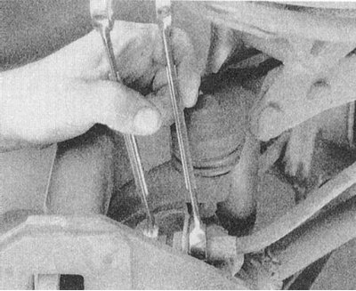


6. The nipple connector is disconnected using two keys, one of which (a socket wrench with a split head) is placed on the nipple nut, and the second is used to hold the mating part of the joint from turning. Using two keys will avoid extremely undesirable deformations of the hydraulic line and damage to the nipple.
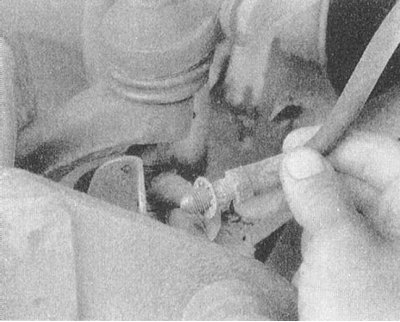


7. Any sealing washers used in nipple connectors must be replaced without fail!


8. After moving the drain container, disconnect the other end of the serviced section of the brake line (also use two wrenches).
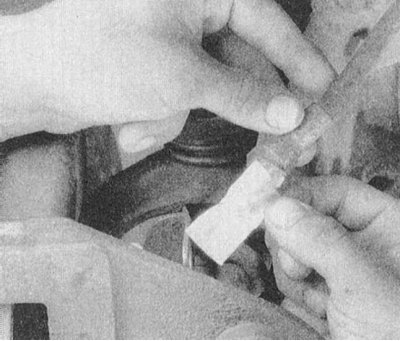


9. Release the disconnected line from the intermediate clamps and remove it from the vehicle. Immediately plug the open ends of the disconnected line.

Installation


1. When installing a replaceable section of the brake line, start by connecting the end that is farthest from the master cylinder. When screwing on the union nut, make sure that it does not become warped, which could result in thread stripping.

2. Tightening of the nipple connectors is also done using two keys.

3. After installing the replacement section, make sure that it does not come into contact with moving suspension/steering components (a minimum of 13 mm of removal is considered safe).

4. Ensure that the line is secured to all provided intermediate clamps/support brackets.

Note: When installing flexible brake hoses, make sure that they are not twisted.


5. Reinstall all components removed for access, then lower the vehicle to the ground.

6. Add the required amount of fresh hydraulic fluid to the master cylinder reservoir (see Chapter Settings and ongoing maintenance), and bleed the brake system (see Section Bleeding the brake system).
This article is available at: russian, bulgarian, belarusian, ukrainian, serbian, croatian, romanian, polish, slovak, hungarian
This article was reviewed by: Dmitry Vasiliev
Share with friends:
◀ Previous
Galant 6 and 7: Brake system
Next ▶

Removal and installation the regulator valve
Checking the serviceability and tightness, removing and installing the brake booster
Adjusting the foot brake pedal
Removal and installation the master brake cylinder
Replacing the brake light switch sensor
Bleeding the brake system
Disc brakes — general information
Evaluation of the condition of brake pads
Replacing disc brake pads
Removal and installation of disc brake calipers
Similar materials for other Mitsubishi models

➤ Checking the brake fluid level Mitsubishi Colt 4 and 5 (1991-2003)
➤ Checking the brake fluid level Mitsubishi Lancer 3 and 5 (1984-1992)
➤ Parking (hand) brake Mitsubishi L200 4 (2005-2014, diesel)
➤ Parking brake Mitsubishi Outlander 1 (2003-2008)
➤ Parking brake Mitsubishi Pajero 1 and 2 (1982-1999)
➤ Brake fluid Mitsubishi Carisma (1995-2004)
Link in different formats to this article
Comments and feedback from visitors
No comments yet


Add up two numbers 45 + 15


Galant 6 and 7 (1987-1998) 
  • General information
  • Introduction to guide
  • User manual
  • Driving and operation
  • Maintenance
  • Power unit
  • Dismantling the engine
  • Engine overhaul
  • Cooling and heating
  • Power and exhaust systems
  • Engine electrical equipment
  • Engine management systems
  • Transmission
  • Mechanical gearbox
  • Automatic gearbox
  • Clutch
  • Drive shafts and transfer case
  • Chassis and running gear
  • Brake system
  • Car suspension
  • Steering
  • Body and interior
  • Exterior (external elements)
  • Interior (internal elements)
  • Doors, locks and windows
  • Electrical equipment
  • Equipment and devices
  • Wiring diagrams Galant
  • Wiring diagrams Mirage
  • Wiring diagrams Diamante
Galant 5 (1983-1989, petrol) 
  • General information
  • Troubleshooting
  • Maintenance
  • Power unit
  • Engine repair
  • Engine overhaul
  • Cooling and heating
  • Fuel and exhaust system
  • Engine electrical equipment
  • Reducing exhaust toxicity
  • Transmission
  • Manual gearbox
  • Automatic gearbox
  • Clutch and drive shafts
  • Chassis and running gear
  • Brake system
  • Car suspension
  • Steering
  • Body and interior
  • Exterior (external elements)
  • Interior (internal elements)
  • Doors, locks and windows
  • Electrical equipment
  • Equipment and devices
  • Electrical diagrams
MitsubishiMan.ru © 2018–2026 • Mobile version • Articles about Mitsubishi • Contacts • Sitemap: EN BG BY UA RS HR RO PL SK HU • Site search • Bookmark
Colt 2 and 3 (1983-1993) · Colt 4 and 5 (1991-2003) · Colt 5 (1995-2003) · Lancer 3 and 5 (1984-1992) · Lancer 9 (2000-2007) · Galant 5 (1983-1989) · Galant 6 and 7 (1987-1998) · L200 4 (2005-2014) · Outlander 1 (2003-2008) · Pajero 1 and 2 (1982-1999) · Pajero 4 (2006-2021) · Carisma (1995-2004) · Space Star (1998-2005) ·
This resource sets cookies 🍪 to avoid bothering you with repeated data entry.