
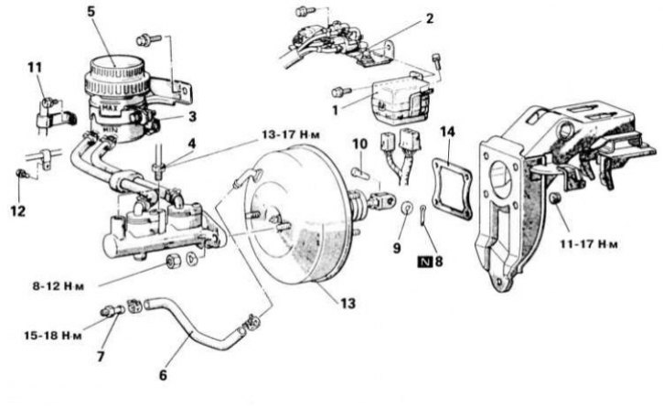
Details of installation of assembly of the vacuum amplifier of brakes
1 - Mounting block for the relay of the air conditioning system; 2 - Solenoid valve; 3 - Contact connector for electrical wiring of the brake fluid level sensor; 4 - Brake tube; 5 - Assembly of the GTZ with a reservoir; 6 - Vacuum hose with built-in control valve; 7 - Fitting; 8 - Cotter pin; 9 - Washer; 10 - Pin; 11 - Bolt of the support bracket of the return hydraulic tube; 12 - Bolt of the hydraulic tube support bracket; 13 - Assembling the vacuum booster; 14 - Sealing gasket; N - Replace
Note. The vacuum brake boost servo does not need regular maintenance, except for periodic checks of the condition of the vacuum hose.
Functional check
While holding the foot brake pedal depressed, start the engine. If immediately after starting the pedal slightly "fails", therefore, the vacuum brake booster is working properly.
Leak test
1. Run the engine for a couple of minutes, then shut it off. Slowly depress the foot brake pedal several times. If the pedal stroke gradually decreases with each squeeze, stabilizing at the third or fourth stroke, then the tightness of the vacuum booster assembly is not broken.
2. Depress the foot brake pedal while the engine is running. Keeping the pedal depressed, turn off the engine. If after 30 seconds of keeping the pedal depressed, its reserve stroke does not change, therefore, the tightness of the vacuum booster assembly is not broken.
Removing
1. The vacuum brake booster unit cannot be repaired and must be replaced as an assembly in case of failure. Assembly installation details are shown in the illustration.
2. Disconnect the vacuum hose connected to the booster from the engine intake manifold. Be careful not to damage the hose when removing it from the fitting on the booster assembly.
3. Give the fixing nuts and carefully remove the main brake cylinder from the assembly of the vacuum booster (see Section Removal and installation of GTZ), - take care not to kink or twist the hydraulic lines.
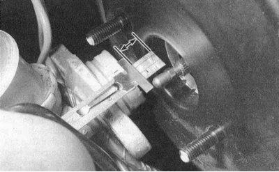
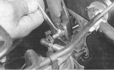
4. In the passenger compartment, find the node for connecting the pusher rod of the vacuum booster to the foot brake pedal, - (use a flashlight if necessary). Remove the cotter pin, release the roll pin and disconnect the split finger of the pusher from the pedal lever.
5. From the passenger compartment on the left under the instrument panel, release the four nuts securing the vacuum booster assembly to the bulkhead of the engine compartment - if necessary, use a flashlight.
6. Go to the engine compartment and remove the vacuum booster assembly from the rear bulkhead. Pull the assembly strictly along the axis of its installation until the pusher rod is completely released. Remove the assembly from the engine compartment.
Installation and adjustment
1. Installation is carried out in the reverse order. Tighten all fasteners to the required torque. Don't forget to replace the split pin that secures the push rod to the pedal. Track reliability of fixing of a returnable spring.
2. When replacing the vacuum booster, check / adjust the installation dimensions:
- a) Measure the amount of protrusion of the pusher above the mating surface of the vacuum booster assembly with the GTZ. Write down the result of the measurement, designating it as a size "A";
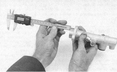
- b) Measure the distance from the mating surface of the mounting flange to the end of the GTZ. Write down the result of the measurement, designating it as a size "IN";
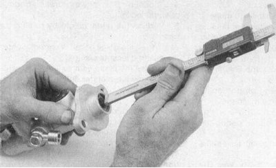
- c) Measure the distance from the end of the GTZ to the bottom of the pocket in the piston for the fit of the pusher rod. Write down the result of the measurement, designating it as a size "WITH";
- d) To obtain the seat clearance of the push rod, subtract dimension B from dimension C, then subtract dimension A from the result;
- e) Compare the result of the calculation with the requirements of the Specifications, if necessary, make an appropriate adjustment to the length of the pusher (see below). If dimension A is less than the pocket depth in the GTZ piston (C - B), the stem must be shortened, otherwise lengthened.
 |  |
 |
3. If the seat gap is out of range, loosen the knurled bit on the end of the stem and turn the adjusting rod until the desired result is achieved. After completing the adjustment, tighten the locknut firmly and recheck.
4. Install in place in the GTZ and connect the vacuum hose to the vacuum booster assembly. Track reliability of a tightening of a collar of fastening of a hose on the receiving union.
5. Adjust the installation height and free play of the foot brake pedal (see Section Foot brake pedal adjustment).
6. Before starting the operation of the car, make sure that the brake system is functioning properly.