



Contents: Gasoline Engine Generator 1600 ⤓ Generator for petrol engines 1600 6V…⤓ Diesel Engine Generator F9Q ⤓ Disassembling the generator ⤓ Assembly ⤓ Checking the rotor ⤓ Stator check ⤓ Checking the rectifier unit ⤓ Replacing brushes ⤓
Gasoline Engine Generator 1600
Removal
To remove, follow these steps in sequence.
1. Remove the air conditioning compressor and power steering pump drive belt.
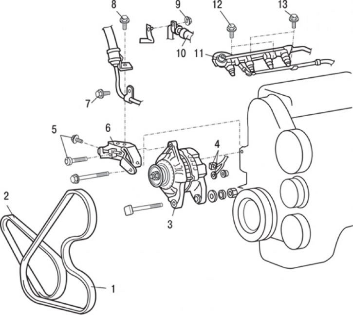
Fig. 9.4. Generator for 1.6 l petrol engines: 1 – air conditioning compressor and power steering pump drive belt; 2 – generator drive belt; 3 – generator; 4 – generator connector; 5 – bolt (20–25 Nm); 6 – generator adjustment bar; 7 – bolt (25 Nm); 8 – oil line pipe retainer bolts (25 Nm); 9 – nut (14 Nm); 10 – Air conditioning hose connection; 11 – Fuel rail and fuel return hose assembly (DOHC engine); 12 – bolt (10–13 Nm); 13 – bolt (10 Nm)
2. Loosen the tension and remove the generator drive belt 2 (Fig. 9.4).
3. Unscrew the oil line pipe retainer bolts 7, 8.
4. Unscrew the air conditioner hose connection fastening nut 10.
5. Loosen the bolts and remove the fuel rail and fuel return hose assembly (DOHC engine) 11.
Attention! Be especially careful and gentle when removing the fuel rail – do not drop the injectors on the floor.
6. Loosen the bolts and remove the generator adjusting bar 6.
7. Disconnect the electrical connectors from the generator 4.
8. Unscrew the nuts, remove the lower generator mounting bolt and remove the generator 3. Slightly move apart the parts and elements that interfere with the removal of the generator.
Installation
Installation is carried out in the reverse order of removal.
Adjust the tension of the generator drive belt.
Generator for petrol engines 1600 6V and 1800
Removal
To remove, follow these steps in sequence.
1. On vehicles with air conditioning, install a ratchet wrench on the alternator tension bar.
2. Loosen the generator mounting bolts.
3. Slowly loosen the alternator belt tension, then remove the belt.
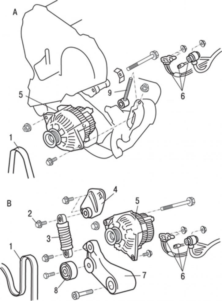
Fig. 9.5. Generator for gasoline engines 1600 6V and 1800: A - cars without air conditioning; B – cars with air conditioning; 1 – generator drive belt; 2 – bolt; 3 – spring; 4 – generator tension bar; 5 – generator; 6 – Generator connectors and connections; 7 – tensioner; 8 – pulley; 9 – bolt
4. Disconnect the electrical connectors of generator 6 (Fig. 9.5).
5. Loosen the generator tension bar mounting bolt 2.
6. Loosen the nut of the adjusting bolt 9.
7. Loosen the bolts and remove the generator tension bar 4.
8. Loosen the bolts and remove pulley 8.
9. Loosen the bolts and remove tensioner 7.
10. Loosen the nuts, remove the generator mounting bolt and remove the generator 5.
Installation
Installation is carried out in the reverse order of removal.
1. On vehicles with air conditioning, place the drive belt over the pulleys.
2. Install a ratchet wrench on the alternator tension bar and tighten the belt, making sure the belt is positioned correctly on the pulleys.
3. Tighten both bolts.
4. Adjust the tension of the generator drive belt.
Diesel Engine Generator F9Q
Removal
To remove, follow these steps in sequence.
1. Remove the protective cover.
2. Remove the intercooler air hose.
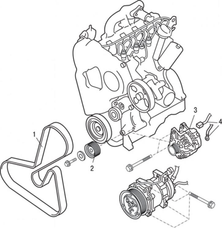
Fig. 9.6. Diesel engine generator F9Q: 1 – drive belt; 2 – idle guide pulley; 3 – generator; 4 – generator connector
3. Loosen the tension and remove drive belt 1 (Fig. 9.6).
4. Loosen the bolt and remove the idle guide pulley 2.
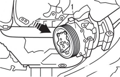
Fig. 9.7. Moving the air conditioning compressor (1) when removing the generator
5. Loosen the air conditioner compressor mounting bolt. Move the air conditioner compressor so that there is enough space to remove the generator to avoid damage (Fig. 9.7).
6. Disconnect the electrical connectors of generator 4 (see Fig. 9.6).
7. Loosen the nuts, remove the generator mounting bolts and remove the generator 3.
Installation
Installation is carried out in the reverse order of removal.
1. Install the intercooler air hose.
2. Install the intercooler.
3. Install the protective cover.
Disassembling the generator
To disassemble, perform the following operations in sequence.
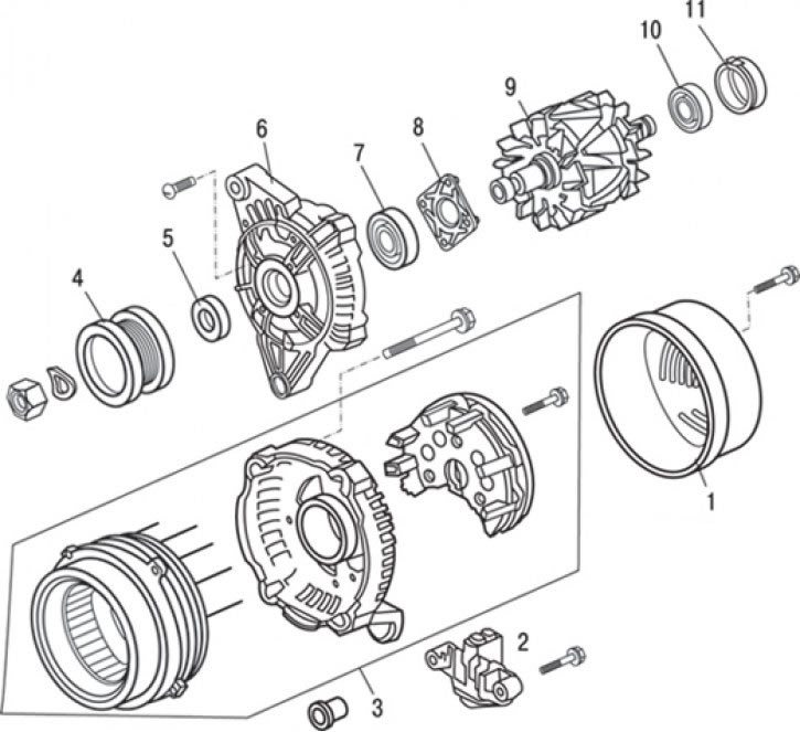
Fig. 9.8. Generator elements: 1 – generator rear protective cover; 2 – brush holder assembly; 3 – stator and rectifier block assembly; 4 – generator pulley; 5 – spacer washer; 6 – front cover; 7 – front bearing; 8 – bearing holder; 9 – rotor assembly; 10 – rear bearing; 11 – bearing cover
1. Loosen the screws and remove the rear protective cover of the generator 1 (Fig. 9.8).
2. Loosen the screws and carefully remove the brush holder assembly 2.
3. Loosen the screws, remove the stator and rectifier block assembly 3.
4. Remove bearing cover 11.
5. Secure the front generator bracket in a soft jaw vice.
6. Use the special tool and socket wrench to fix the nut. Then fix the rotor shaft with the hex key and loosen the nut. Unscrew the nut and remove pulley 4.
7. Remove spacer washer 5.
8. Remove the rotor assembly 9.
9. Remove the rear bearing 10.
10. Remove bearing holder 8.
11. Remove the front bearing 7.
Assembly
Assembly is carried out in the reverse order of removal.
1. Secure the front generator bracket in a soft jaw vice.
2. Use the special tool and socket wrench to fix the nut. Then use the hex key to fix the rotor shaft and tighten the nut.
Checking the rotor
1. Check for breakage in the rotor winding. Check the circuit between the slip rings of the generator rotor.
2. If the resistance is too low (tends to 0), this means there is a short circuit. In case of a break in the rotor winding circuit or a short circuit, replace the rotor assembly.
Resistance is about 2.6 Ohm.
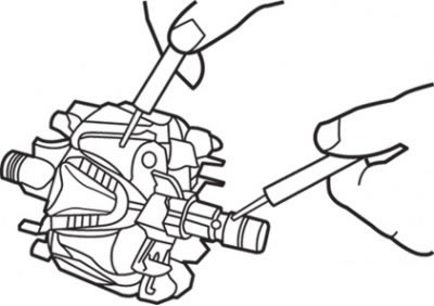
Fig. 9.9. Checking the electrical circuit between the slip ring and the generator core
3. Check for a short circuit of the rotor winding to ground (Fig. 9.9). Check the circuit between the slip ring and the core. If the circuit is shorted (short circuit to ground), replace the rotor assembly.
Stator check
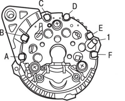
Fig. 9.10. Location of stator winding terminals: 1 – terminal "B"
1. Check the stator winding. Check that there is no open circuit between the terminals ("A" – "B"), ("C" - "D") and ("E" – "F") (Fig. 9.10).
2. If the winding circuit is open (resistance tends to infinity), then replace the stator and rectifier unit as a whole.
3. Check for short circuit of stator winding to ground. Make sure that the circuit between each terminal of stator winding and core is open.
4. If the circuit is closed (resistance tends to zero), replace the stator and rectifier unit as an assembly.
Checking the rectifier unit
1. Check the condition of the circuits between terminal "B" and the stator winding terminals ("A", "C" and "E") (see Fig. 9.10). A short circuit in both directions means a diode breakdown, so it is necessary to replace the stator and rectifier unit as a whole.
2. Check the condition of the circuits between the stator winding terminals ("B", "D", "F" and "ground"). A short circuit in both directions means a diode breakdown, so it is necessary to replace the stator and rectifier unit as a whole.
Replacing brushes
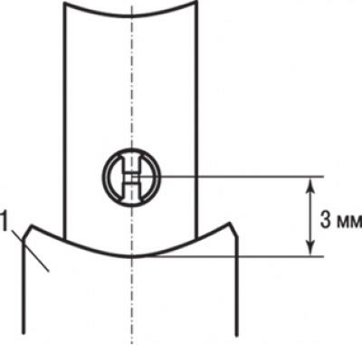
Fig. 9.11. Checking the wear of the generator brushes: 1 – brush holder
If the brush is worn down to the center of the mark (3 mm from the center of the brush holder), replace the brush holder assembly (Fig. 9.11).