
English Русский
Български
Беларускі
Український
Српски
Hrvatski
Română
Polski
Slovenský
Magyar
Articles Bookmark Contacts Sitemap   
Company Audi Company Ford Company Hyundai Company Kia Company Mazda Company Mercedes-Benz Company Nissan
MitsubishiMan.ru


Home Colt Lancer Galant L200 Outlander Pajero Others
Carisma (1995-2004) Space Star (1998-2005)

Checking the generator output current (Mitsubishi Carisma)

  • Home
  • Mitsubishi
  • Carisma (1995-2004)
  • Power unit
  • Engine electrical equipment
  • Checking the generator output current
0
This test determines whether the generator output current matches the rated value.

1. Before starting the test, check:
  • installation of a generator;
  • battery;
  • alternator drive belt tension;
  • fusible link;
  • absence of extraneous noise from the generator when the engine is running.

2. Turn off the ignition.

Caution! The battery must be slightly discharged. The load created by a fully charged battery is insufficient to accurately perform this test.


3. Disconnect the cable from the negative terminal of the battery.
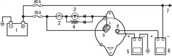


Fig. 9.2. Generator output current test diagram: 1 – battery; 2 – ignition switch; 3 – low battery indicator light; 4 – generator relay; 5 – voltmeter; 6 – ammeter; 7 – load


4. Disconnect the wire from the "B" terminal of the generator. Connect the wire from the "+" terminal of a DC ammeter with a measurement range of 0–100 A to the "B" terminal of the generator, and then the wire from the "–" terminal of the ammeter to the wire disconnected from the "B" terminal of the generator (Fig. 9.2).

Warning! Do not use clamps (crocodile clips) when connecting to an electrical circuit. Tighten the connections with bolts and nuts. Otherwise, a bad connection (using crocodile clips) may cause a serious malfunction or an accident due to high current.


Attention! It is recommended to use an ammeter with an inductive type sensor ("current clamp"), which allows you to measure the current without disconnecting the wire from the "B" terminal of the generator.


5. Connect the wire from the "+" of the voltmeter with a 0–20 V scale to the "B" terminal of the generator, and the wire from the "–" of the voltmeter to the "ground".

6. Connect the tachometer.

7. Connect the previously disconnected wire to the negative terminal of the battery.

8. Leave the hood open.

9. Check the voltage shown by the voltmeter. It should be equal to the battery voltage.

Warning! If the voltmeter shows 0 V, the probable cause is a break in the circuit (including the fuse) between the generator terminal "B" and the positive terminal of the battery.


10. Under the steering wheel exterior lighting switch, turn on the headlights, and then start the engine.

11. Immediately after turning on the high beam headlights and turning on the heater fan to maximum speed, increase the engine crankshaft speed to 2500 min⁻¹ and read the maximum value of the generator output current (shown by the ammeter).

The maximum permissible value is 70% of the rated output current.

Since the current generated by the generator drops rapidly after the engine is started, the test must be performed as quickly as possible in order to measure the maximum value of the output current.

The magnitude of the output current will depend on the electrical load and the temperature of the generator housing.

If the electrical load is low during the test, the specified value of the generator output current will not be achieved, despite the fact that the generator is in good condition. In such cases, to increase the electrical load (in order to discharge the battery), turn on the high beam headlights for a while or connect the external lighting of another car, and then repeat the test.


The specified value of the generator output current may not be obtained also as a result of overheating of the generator housing or too high ambient air temperature. In such cases, let the generator cool down and perform the test again.

The ammeter readings should be above the maximum permissible value. If the ammeter readings are below the maximum permissible value and the generator terminal "B" circuit is in good condition, remove the generator from the vehicle and test it on a bench.

12. After checking, let the engine idle.

13. Turn off the ignition.

14. Disconnect the cable from the negative terminal of the battery.

15. Disconnect the ammeter, voltmeter and tachometer.

16. Connect the standard wire to the generator terminal "B".

17. Connect the negative cable to the battery.
This article is available at: russian, bulgarian, belarusian, ukrainian, serbian, croatian, romanian, polish, slovak, hungarian
This article was reviewed by: Dmitry Vasiliev
Share with friends:
◀ Previous
Carisma: Engine electrical equipment
Next ▶

Checking the generator output voltage drop
General information about the engine electrical equipment
Specifications and data
Checking the voltage regulator
Generator — removal, inspection and installation
Starter — Checking and testing
Direct Drive Starter — Disassembly, Checking and Assembly
Starter with reduction gear — disassembly, inspection and assembly
Similar materials for other Mitsubishi models

➤ Checking the output voltage of the wheel speed sensor Mitsubishi Colt 5 (1995-2003, petrol)
➤ Checking the generator output current Mitsubishi Lancer 9 (2000-2007, petrol)
➤ Checking, removing and installing the generator Mitsubishi Galant 6 and 7 (1987-1998)
➤ Checking and adjusting the tension of auxiliary drive belts Mitsubishi L200 4 (2005-2014, diesel)
➤ Checking the generator output current Mitsubishi Outlander 1 (2003-2008)
➤ Generator repair — checking brushes Mitsubishi Pajero 4 (2006-2021)
Link in different formats to this article
Comments and feedback from visitors
No comments yet


Add up two numbers 29 + 30


Carisma (1995-2004) 
  • General information
  • User manual
  • Maintenance
  • Power unit
  • Petrol engines 4G9
  • Diesel engines FBQT
  • Diesel engines F9Q
  • Cooling system
  • Injection system (MPI)
  • Injection system (GDI)
  • Engine electrical equipment
  • Transmission
  • Clutch
  • Mechanical gearbox
  • Automatic gearbox
  • Chassis and running gear
  • Steering
  • Brake system
  • Front suspension and shafts
  • Rear suspension
  • Body and interior
  • Exterior (external elements)
  • Interior (internal elements)
  • Doors, locks and windows
  • Air conditioner
  • Electrical equipment
  • Equipment and devices
  • Headlights and lighting
  • Electrical circuits
Space Star (1998-2005) 
  • General information
  • User manual
  • Maintenance
  • Power unit
  • Petrol engines 4G9
  • Petrol engines 4G1
  • Diesel engines F9Q1
  • Cooling system
  • Fuel injection system GDI
  • Fuel injection system MPI
  • Diesel supply system F9Q1
  • Ignition system
  • Diesel preheating
  • Transmission
  • Clutch
  • Mechanical gearbox
  • Automatic gearbox
  • Chassis and running gear
  • Suspension and drive shafts
  • Brake system
  • Steering
  • Body and interior
  • Exterior (external elements)
  • Interior (internal elements)
  • Doors, locks and windows
  • Heating and air conditioning
  • Electrical equipment
  • Power devices
  • Equipment and devices
MitsubishiMan.ru © 2018–2026 • Mobile version • Articles about Mitsubishi • Contacts • Sitemap: EN BG BY UA RS HR RO PL SK HU • Site search • Bookmark
Colt 2 and 3 (1983-1993) · Colt 4 and 5 (1991-2003) · Colt 5 (1995-2003) · Lancer 3 and 5 (1984-1992) · Lancer 9 (2000-2007) · Galant 5 (1983-1989) · Galant 6 and 7 (1987-1998) · L200 4 (2005-2014) · Outlander 1 (2003-2008) · Pajero 1 and 2 (1982-1999) · Pajero 4 (2006-2021) · Carisma (1995-2004) · Space Star (1998-2005) ·
This resource sets cookies 🍪 to avoid bothering you with repeated data entry.