
Checking and adjusting the axial clearance of the direct gear starter gear
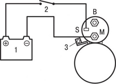
Pic. 9.12. Scheme for checking and adjusting the axial clearance of the direct gear starter gear: 1 - rechargeable battery; 2 - switch; 3 - stator excitation wire
1. Disconnect the stator winding wire from the terminal «M» traction relay (pic. 9.12).
2. Connect the wires from the battery terminals to the terminals «S» And «M» traction relay as shown in Figure 9.12.
3. Turn the key in the ignition switch to position «ON» («ON»), while the drive gear will extend to the stop.
Attention! This check must be carried out quickly, no longer than 10 s, to prevent the winding from burning out.
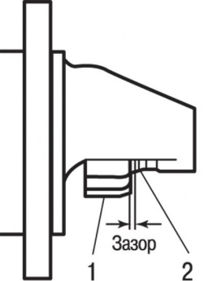
Pic. 9.13. Measuring the axial clearance between the drive gear and the stop ring: 1 - gear; 2 - restrictive ring
4. Using a feeler gauge, measure the axial clearance between the drive gear and the stop ring (pic. 9.13). It should be in the range of 0.5–2.0 mm.
5. If the axial clearance is outside the nominal range, adjust it by setting (withdrawals) shims between the traction relay and the front cover.
Checking the solenoid winding of the relay
1. Disconnect the stator winding wire from the terminal «M» traction relay.
2. Connect the wires from the battery terminals to the terminals «S» And «M» as shown in Figure 9.12.
Attention! This check must be carried out quickly, within no more than 10 s, in order to prevent the winding from burning out.
If the drive gear extends, then the pull-in winding is OK. If not, replace the traction relay.
Checking the holding winding of the traction relay
1. Disconnect the stator winding wire from the terminal «M» traction relay.
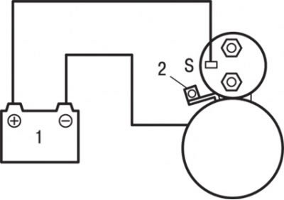
Pic. 9.14. Checking the holding winding of the traction relay: 1 - rechargeable battery; 2 - excitation winding wire
2. Connect the wires from the battery terminals to the terminal «S» and starter housing as shown in Fig. 9.14.
Attention! This check must be carried out quickly, within no more than 10 s, in order to prevent the winding from burning out.
3. Manually extend the drive gear until it stops (to the limit ring).
4. If the drive gear remains in the extended position, then the retaining coil is good. If the gear retracts, then there is a break in the holding winding. In this case, replace the traction relay.
Idle test
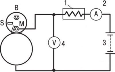
Pic. 9.15. Scheme for testing in idle mode: 1 - rheostat; 2 - ammeter; 3 - storage battery; 4 - voltmeter
1. Clamp the starter in a soft-jawed vise and connect the wires from a fully charged battery to its terminals as follows: connect in series between terminal «M» starter motor and battery positive ammeter (with a scale of 100 A) and a carbon sliding contact rheostat, as shown in fig. 9.15.
2. Connect a voltmeter with a scale of 15 V in parallel with the stator winding circuit.
3. Set the rheostat slider to the position of maximum resistance.
4. Connect a wire from the negative plug of the storage battery to the case of a starter.
5. Using a rheostat, set the voltage of the voltmeter to 11.5 V.
6. Check that the maximum current consumption is not more than 60 A, and also that the starter armature rotates freely, without jerking or jamming.
Relay armature return test
1. Disconnect the stator winding wire from the terminal «M» traction relay.
2. Connect the battery to the terminal «M» and starter housing (see fig. 9.14).
Attention! This check must be carried out quickly, no more than 10 s, in order to prevent the winding from burning out.
Extend the drive gear by hand and release. If the gear immediately returns to its original position, then the traction relay is working properly. If not, replace the traction relay.
Attention! Be careful not to pinch your fingers.