
Disassembly
To disassemble, perform the following steps in sequence.
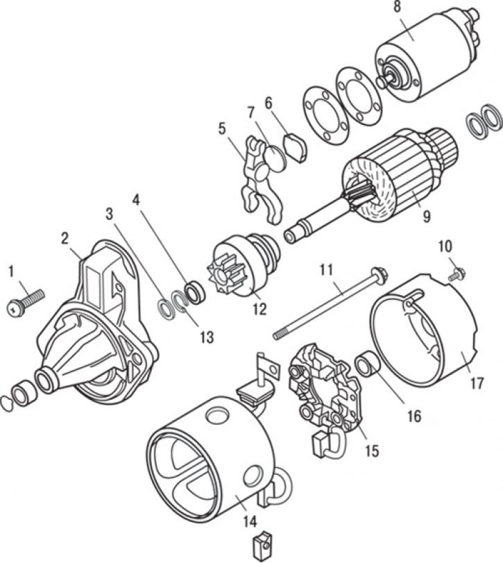
Pic. 9.16. Direct Drive Starter: 1 - screw; 2 - front cover; 3 - washer; 4 - restrictive ring; 5 – drive lever; 6 - plate; 7 - gasket; 8 - traction relay; 9 – starter anchor; 10 - screw; 11 – coupling bolt; 12 - freewheel; 13 - retaining ring; 14 – pole assembly with stator winding; 15 - brush holder assembly; 16 - rear bearing; 17 - back cover
1. Remove screws 1 (pic. 9.16) and remove the traction relay 8.
2. Remove gasket 7 and plate 6.
3. Unscrew the screws 10 and remove the rear cover 17.
4. Turn away coupling bolts 11.
5. Remove rear bearing 16.
6. Remove brush holder assembly 15.
7. Remove the complete pole with stator winding 14.
8. Remove starter anchor 9.
9. Remove drive lever 5.
10. Remove washer 3.
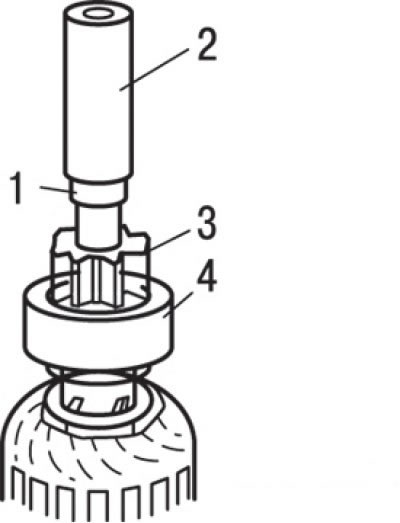
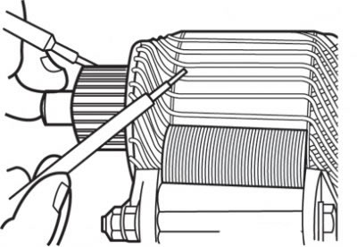
Pic. 9.17. Moving down the restrictive ring: 1 - restrictive ring; 2 - mandrel; 3 - drive gear; 4 - freewheel
11. Using a suitable socket, slide the stop ring down (pic. 9.17).
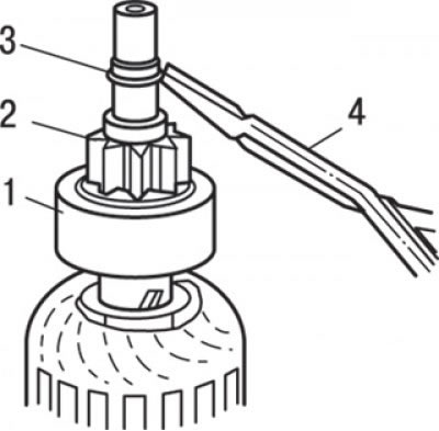
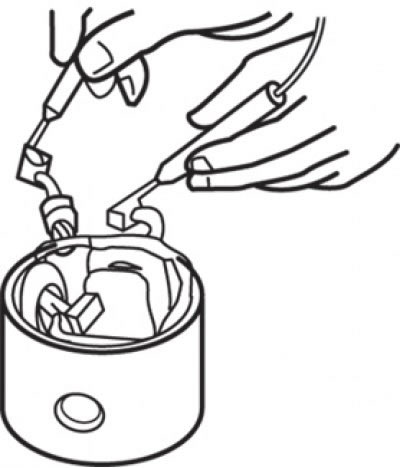
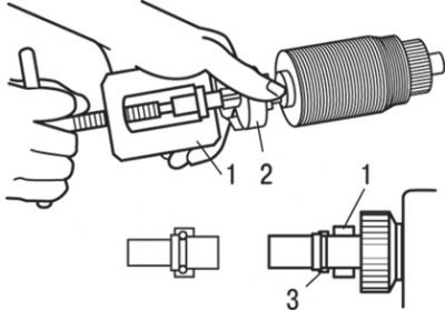
Pic. 9.18. Removing the restrictive ring: 1 - freewheel; 2 - drive gear; 3 - retaining ring; 4 - special pliers for removing retaining rings
12. Using special pliers, remove the limit ring, then the limit ring and freewheel (pic. 9.18).
Cleaning the starter
Do not soak parts in cleaning solutions (solvents). Such washing of the pole assembly with the stator and/or armature windings will damage the insulation of the windings. Wipe these parts with a cloth only.
Do not immerse freewheel assembly with drive gear in cleaning solution (solvent). The freewheel has grease lubricated at the factory, so the solvent will flush the grease out of the clutch.
The freewheel assembly with the drive gear can be wiped with a brush dampened with detergent solution and then wiped dry with a cloth.
Manifold check
1. Place the starter armature on two V-shaped supports and measure the radial runout of the manifold with a pointer type indicator, which should be no more than 0.05 mm (limit value - 0.1 mm).
2. Measure the outside diameter of the manifold.
- The nominal value is 32.0 mm.
- The maximum allowable value is 31.0 mm.
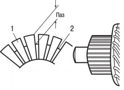
Pic. 9.19. Manifold lamella protrusion measurement: 1 - collector lamellas; 2 - insulator
3. Check the protrusion of the collector lamellas above the insulator (pic. 9.19).
- The nominal value is 0.5 mm.
- The maximum allowable value is 0.2 mm.
Check for an open in the stator winding
Pic. 9.20. Check for an open in the stator winding
If the circuit between the brushes is closed, then the excitation winding is working (pic. 9.20).
Checking the absence of a short circuit in the stator winding «mass»
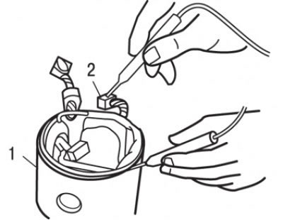
Pic. 9.21. Checking the absence of a short circuit in the stator winding to ground: 1 – pole assembled with stator winding; 2 - brush
Using an ohmmeter, measure the resistance between brush and pole (stator housing) (pic. 9.21). If the resistance tends to infinity, then the stator winding shorts to «mass» No.
Checking the brush holder
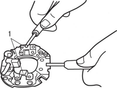
Pic. 9.22. Brush holder check: 1 - brush holder plate
Using an ohmmeter, measure the resistance between the brush holder plate and the brush holder as shown in fig. 9.22. If the resistance tends to infinity, then the brush holder is working.
Checking the freewheel
1. Hold the freewheel housing with your hand and rotate the drive gear. The gear should rotate smoothly, without jamming, in one direction, and not rotate in the opposite direction. If the gear is sticking or turns in both directions, replace the freewheel assembly.
2. Check drive gear for excessive wear or nicks. If any are found, replace the freewheel assembly. If the drive gear is damaged, also check the flywheel/torque converter ring gear (AKP) for scoring or excessive wear.
Checking the bushings of the front and rear covers
Check bushings for wear and tear. If found, replace the front or rear starter cover assembly.
Brush and spring replacement
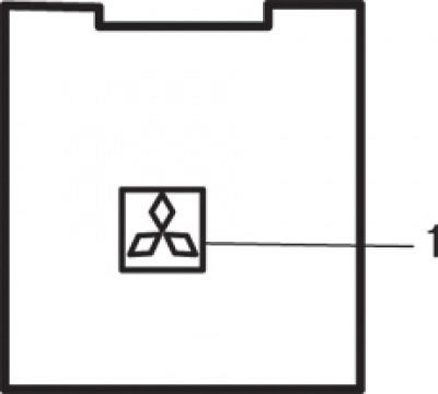
Pic. 9.23. Line location (1) starter brush wear limit
Worn below the limit line or oily brushes should be replaced (pic. 9.23).
1. To replace the brushes, be careful not to damage the wires of the brushes, crush the old brushes with pliers.
2. Sand the end of the brush wire with sandpaper to ensure a strong solder.
3. Insert the conductor into the hole of the new brush and solder it. At the same time, make sure that the end of the conductor and excess solder do not protrude beyond the surface of the brush.
4. When replacing the negative brush, pull the brush out of the brush holder by pulling back on the retaining spring.
Checking the short circuit of the armature winding
1. Install the anchor in the growler (starter and alternator winding tester).
2. While slowly rotating the anchor in the growler, keep a thin steel plate parallel and just above the anchor. If the armature winding is faulty (short circuit), then the plate will vibrate and be attracted to the core. Replace defective anchor.
Checking the short circuit of the armature winding for «mass»
Pic. 9.24. Checking the short circuit of the armature winding for «mass»
Using an ohmmeter, measure the resistance between each commutator lamella and the armature core (pic. 9.24). If the resistance tends to infinity, then the insulation is good.
Checking for an open in the armature winding
Using an ohmmeter, measure the resistance between the collector fins.
If there is little resistance (circuit is closed), then the armature winding is OK.
Assembly
The assembly of the direct drive starter is carried out in the reverse order of disassembly, taking into account the following.
Pic. 9.25. Installation of restrictive and retaining rings: 1 - restrictive ring; 2 - freewheel; 3 - retaining ring
Using a suitable puller, slide the freewheel stop ring onto the retaining ring (pic. 9.25).