
English Русский
Български
Беларускі
Український
Српски
Hrvatski
Română
Polski
Slovenský
Magyar
Articles Bookmark Contacts Sitemap   
Company Audi Company Ford Company Hyundai Company Kia Company Mazda Company Mercedes-Benz Company Nissan
MitsubishiMan.ru


Home Colt Lancer Galant L200 Outlander Pajero Others
Carisma (1995-2004) Space Star (1998-2005)

Diesel engine preheating system (Mitsubishi Carisma)

  • Home
  • Mitsubishi
  • Carisma (1995-2004)
  • Power unit
  • Engine electrical equipment
  • Diesel engine preheating system
0
Contents: Checking the diesel engine…⤓ Checking the glow plug relay unit ⤓ Glow plug ⤓
The diesel engine preheating system reduces the time required for starting at low temperatures and makes it almost equal to the very fast starting of petrol engines.

The electronic engine control unit determines the time during which voltage is supplied to the glow plugs after turning the ignition switch to the "ON" position, as well as the glow time of the control lamp for the pre-heating system of the diesel engine, depending on the temperature of the engine coolant.

When the engine control unit detects a malfunction, it sets a fault code corresponding to the malfunction (related to the fuel supply system).

Checking the diesel engine preheating system


1. Check the battery voltage, which should be within 11–13 V.

2. Make sure that the engine coolant temperature is not higher than 40°C.
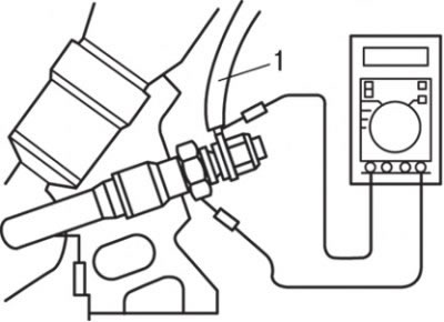


Fig. 9.40. Measuring the resistance between the wire (1) and the glow plug housing


3. Measure the resistance between the wire and the glow plug body ("ground") as shown in Fig. 9.40.

Note: The resistance value is the resistance of two glow plugs connected in parallel.


The nominal resistance value is 0.3 Ohm.
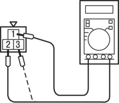


Fig. 9.41. Measuring the resistance at the glow plug relay connector contacts: "1" - "2" - relay 1 (glow plugs 1 and 3); "1" - "3" - relay 2 (glow plugs 2 and 4)


4. Measure the voltage from relay 1 (glow plugs 1 and 3) and from relay 2 (glow plugs 2 and 4) (Fig. 9.41).

When measuring from the glow plug relay 1 side, connect the ohmmeter to the glow plug wire of the third cylinder and to the body ("ground") of the glow plug of the third cylinder.

When measuring from the glow plug relay 2 side, connect the ohmmeter to the glow plug wire of the fourth cylinder and to the body ("ground") of the glow plug of the fourth cylinder.

5. Measure the voltage immediately after turning on the ignition (without starting the engine).

The nominal voltage value is 9-11 V (the voltage decreases to 0 V within 11-22 s).

6. Also make sure that the glow plug indicator light comes on immediately after the ignition is turned on.

Attention! The current "conduction time" changes depending on the coolant temperature when the ignition is on.


7. Measure the voltage while the starter is cranking the engine crankshaft.


The nominal voltage value is not less than 6 V.

8. Start the engine and measure the voltage while the engine is warming up.

9. The voltage always decreases to 0 V within 10-220 s after the engine starts.

The nominal voltage value is 12-15 V.

Checking the glow plug relay unit


1. Disconnect the glow plug wire and all other connectors from the glow plug relay.

2. Measure the resistance at contacts "1"–"2" and "1"–"3" of the glow plug relay connector (see Fig. 9.41).

The nominal resistance value is 27–35 Ohm.

3. Check the operation of the glow plug relay.

When checking relay 1, connect the "+" of the battery to contact "1" of the connector, and the "-" of the battery to contact "2" of the relay connector.

When checking relay 2, connect the "+" of the battery to contact "1" of the connector, and the "-" of the battery to contact "3" of the relay connector.

Caution: Do not ground the terminals of disconnected connectors.


When using jumpers, be especially careful not to mix up the connected terminals. This will cause the relay to fail.

4. Check for continuity at each terminal when the battery + jumper is connected and disconnected.

When testing relay 1, connect an ohmmeter to contacts "1" and "A" (glow plug wire 3) of the single-pin connector.

When checking relay 2, connect an ohmmeter to terminals "1" and "B" (glow plug wire 4) of the single-pin connector.

When connecting the "+" of the battery, the circuit (conductivity between the contacts) is closed, and when disconnected, the circuit is open.

Glow plug


Removal


1. Remove the fuel injectors.
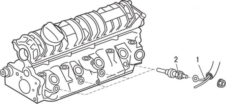


Fig. 9.42. Glow plugs for F8QT engines: 1 – wiring harness connector; 2 – glow plug, 22.5 Nm


2. Disconnect the electrical connector of wire harness 1 (Fig. 9.42, 9.43).
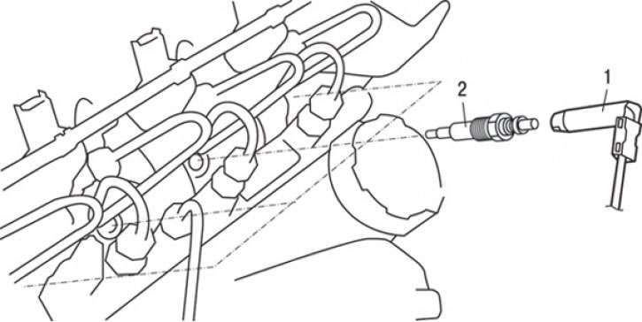


Fig. 9.43. Glow plugs of F9Q engines: 1 – glow plug wire connector connection; 2 – glow plug


3. Unscrew the glow plugs.

Installation


Installation is carried out in the reverse order of removal.
This article is available at: russian, bulgarian, belarusian, ukrainian, serbian, croatian, romanian, polish, slovak, hungarian
This article was reviewed by: Dmitry Vasiliev
Share with friends:
◀ Previous
Carisma: Engine electrical equipment
Next ▶

Knock sensor — removal and installation
DOHC Engine Camshaft and Crankshaft Position Sensors
DOHC Engine Ignition Distributor — Removal and Installation
SOHC Engine Ignition Distributor — Removal, Checking and Installation
Checking and cleaning spark plugs
 
Similar materials for other Mitsubishi models

➤ Diagnostics of faults in the fuel system of a diesel engine Mitsubishi Colt 4 and 5 (1991-2003)
➤ Diagnostics of faults in the fuel system of a diesel engine Mitsubishi Lancer 3 and 5 (1984-1992)
➤ Engine Management System (Galant 2.0L SOHC 1990-1992) Mitsubishi Galant 6 and 7 (1987-1998)
➤ Electronic immobilizer (anti-theft system that blocks… Mitsubishi L200 4 (2005-2014, diesel)
➤ Electronic immobilizer (engine start blocking system) Mitsubishi Outlander 1 (2003-2008)
➤ Removal and installation of a diesel engine Mitsubishi Pajero 1 and 2 (1982-1999)
Link in different formats to this article
Comments and feedback from visitors
No comments yet


Add up two numbers 16 + 39


Carisma (1995-2004) 
  • General information
  • User manual
  • Maintenance
  • Power unit
  • Petrol engines 4G9
  • Diesel engines FBQT
  • Diesel engines F9Q
  • Cooling system
  • Injection system (MPI)
  • Injection system (GDI)
  • Engine electrical equipment
  • Transmission
  • Clutch
  • Mechanical gearbox
  • Automatic gearbox
  • Chassis and running gear
  • Steering
  • Brake system
  • Front suspension and shafts
  • Rear suspension
  • Body and interior
  • Exterior (external elements)
  • Interior (internal elements)
  • Doors, locks and windows
  • Air conditioner
  • Electrical equipment
  • Equipment and devices
  • Headlights and lighting
  • Electrical circuits
Space Star (1998-2005) 
  • General information
  • User manual
  • Maintenance
  • Power unit
  • Petrol engines 4G9
  • Petrol engines 4G1
  • Diesel engines F9Q1
  • Cooling system
  • Fuel injection system GDI
  • Fuel injection system MPI
  • Diesel supply system F9Q1
  • Ignition system
  • Diesel preheating
  • Transmission
  • Clutch
  • Mechanical gearbox
  • Automatic gearbox
  • Chassis and running gear
  • Suspension and drive shafts
  • Brake system
  • Steering
  • Body and interior
  • Exterior (external elements)
  • Interior (internal elements)
  • Doors, locks and windows
  • Heating and air conditioning
  • Electrical equipment
  • Power devices
  • Equipment and devices
MitsubishiMan.ru © 2018–2026 • Mobile version • Articles about Mitsubishi • Contacts • Sitemap: EN BG BY UA RS HR RO PL SK HU • Site search • Bookmark
Colt 2 and 3 (1983-1993) · Colt 4 and 5 (1991-2003) · Colt 5 (1995-2003) · Lancer 3 and 5 (1984-1992) · Lancer 9 (2000-2007) · Galant 5 (1983-1989) · Galant 6 and 7 (1987-1998) · L200 4 (2005-2014) · Outlander 1 (2003-2008) · Pajero 1 and 2 (1982-1999) · Pajero 4 (2006-2021) · Carisma (1995-2004) · Space Star (1998-2005) ·
This resource sets cookies 🍪 to avoid bothering you with repeated data entry.