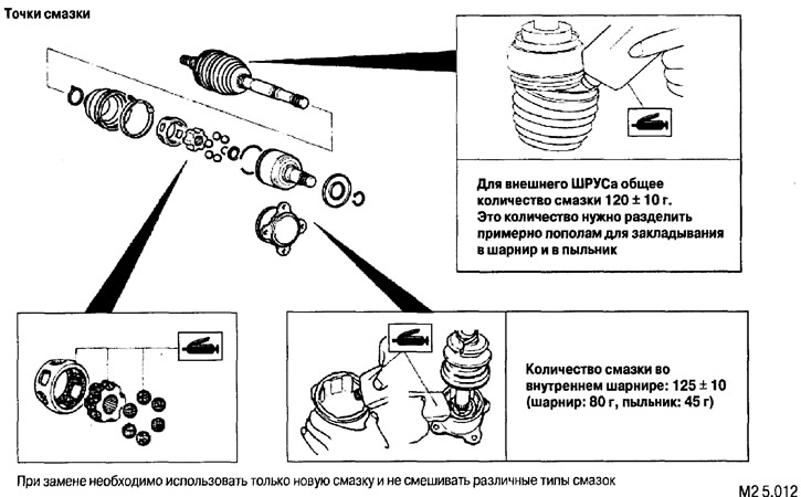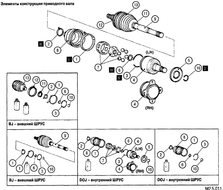
List of design elements of the drive shaft for figure M2 5.011: 1. Large clamp (inner CV joint). 2. Small clamp (inner CV joint). 3. Retaining ring. 4. Inner CV joint housing (the right drive shaft is connected using a flange). 5. Protective ring. 6. Spring retaining ring. 7. Balls with inner race and separator assembly. 8. Dust cover (inner CV joint). 9. Outer CV joint with drive shaft assembly. 10. Retaining ring. 11. Small clamp (outer CV joint). 12. Large clamp (outer CV joint). 13. Housing (outer CV joint). BJ - outer CV joint. DOJ - inner CV joint.
Disassembly is carried out in the order shown in Fig. M2 5.011.
Assembly is performed in the following order: 10, 9, 7, 6, 4, 5, 3, 8, 2, 1.