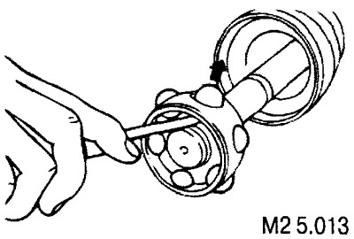
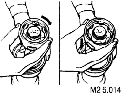
Remove the separator from the inner race.
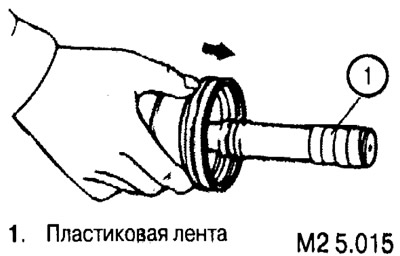
To avoid damage to the boot, cover the spline of the shaft with plastic tape before starting work. Then remove the cover from the shaft in the direction shown in fig. M2 5.015.
Assembling the CV joint and installing the snap ring
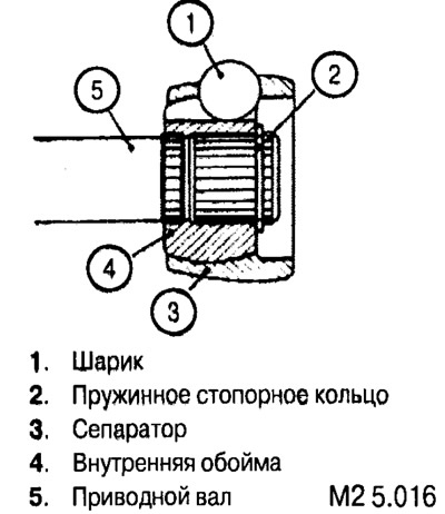
Install all elements of the CV joint (balls, separator, inner race) on the drive shaft and install the circlip into the groove on the drive shaft.
Installing the outer cage (corps) SHRUS
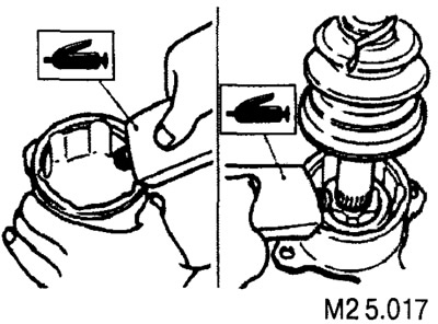
Apply the required amount of lubricant to the inside of the outer race and to the casing (see «Lubrication points»).
Install the retaining ring on the outer race of the hinge, then install the casing on it and fix it with a small tie-down collar.
Installing the boot of the inner CV joint
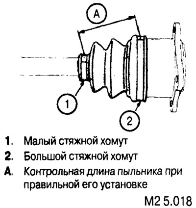
Install the hinge cover so that distance A is 85±3 mm.
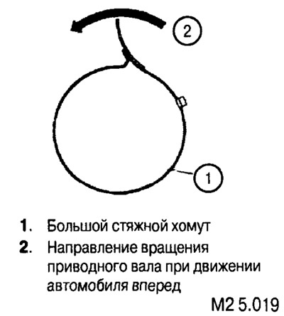
Remove excess air from the casing (if necessary) and install the large tie-down strap on the casing. Pay attention to the correct installation direction of the clamp.
Installation of coupling collars anther SHRUS
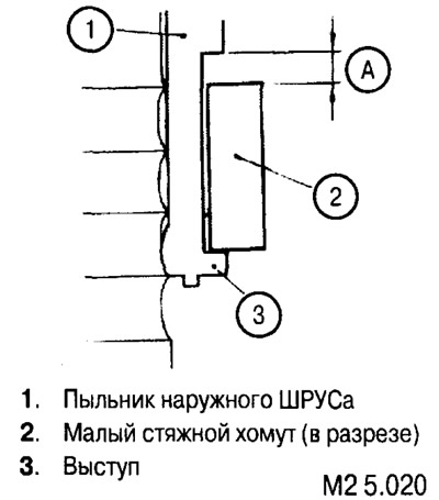
The small tie-down collar must be installed so that it abuts against the protrusion of the anther and provides clearance A (see fig. M2 5.020).
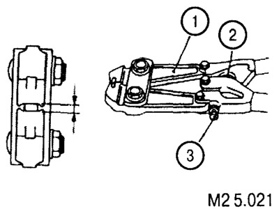
Fixation of the clamps is carried out using a special crimping tool (such as shown in Fig. M2 5.021).
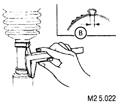
When correctly fixed, the size of the corrugation B should be between 2.4 mm and 2.8 mm.
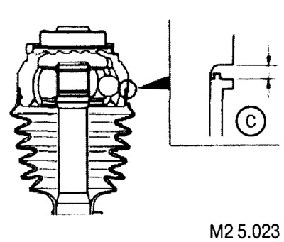
The dust boot must be installed so that dimension C is between 0.05 mm and 1.55 mm.
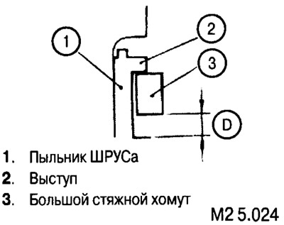
The large tie-down strap must be installed so that it rests against the protrusion of the boot and provides clearance D (see fig. M2 5.024).
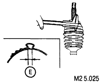
With proper fixation, the size of the corrugation E should be from 2.4 mm to 2.8 mm (see fig. M2 5.025).