
Removing
Note. In order to gain access to the clutch assembly, it is common to remove the transmission while leaving the engine on the vehicle. If the engine has already been removed for general or overhaul, the condition of the clutch components must be checked without fail. Given the relatively low cost of parts and the rather large amount of locksmith work to provide access to the clutch assembly, it makes sense to replace the latter, regardless of the condition of its components. Below is a description of the procedure for removing the clutch without removing the engine from the vehicle.
1. Disconnect the negative cable from the battery.
If the stereo system installed in the car is equipped with a security code, before disconnecting the battery, make sure that you have the correct combination to activate the audio system!
2. Jack up the car and put it on stands.
3. Remove the transmission assembly (see chapter Manual transmission).
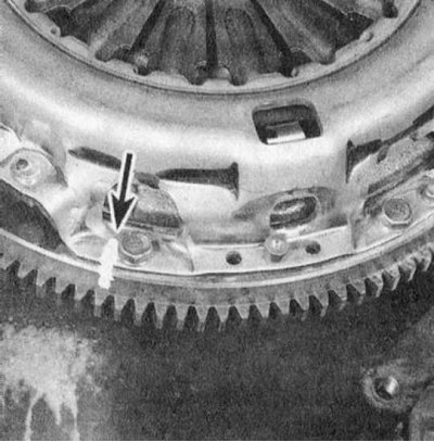
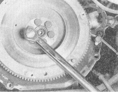
4. Carefully inspect the surfaces of the flywheel and clutch basket assembly for markings (usually in the form of letters X or O applied with white paint). If you cannot find the marking, apply it yourself, clearly marking the position of the basket relative to the flywheel.
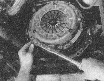
5. Acting in a diagonal order, in several steps (1/4 turn per approach) evenly loosen the bolts securing the clutch basket to the flywheel, fully unloading the diaphragm spring. While firmly supporting the assembly, finally remove the bolts, then separate the basket from the flywheel and remove the assembly from the vehicle.
 |  |
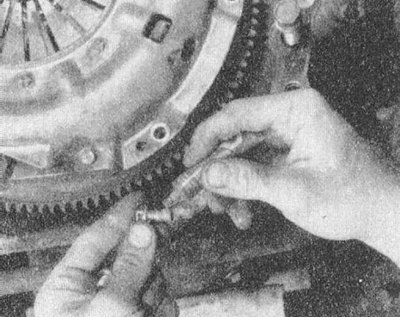
6. Release the retainer and remove the release bearing assembly.
Do not use solvent to clean the release bearing!
7. Assess the condition of the clutch release fork and its bearing surfaces. If necessary, remove the fork and unscrew its spherical support from the gearbox housing.
8. Carefully check the condition of all removed components (see below), replace worn or damaged parts.
Examination
1. Most often, the malfunction of the clutch is associated with wear of the friction linings of the driven disk. However, you should also carefully examine the status of all other components in the assembly.
Note. If there are traces of oil on the surface of the assembly components (polished areas), the cause of the leak should be identified and eliminated, - check the condition of the crankshaft rear oil seal and the gearbox input shaft oil seal, if necessary, replace the defective components.
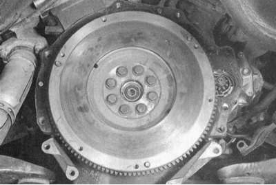
2. Inspect the flywheel running surface for signs of deformation, cracks, overheating, gouges, or other damage. Minor defects can be eliminated by turning in the conditions of a car service workshop (the groove is recommended to be made regardless of the state of the surface). A description of the procedures for removing and installing the flywheel is given in Section Removal and installation of a flywheel/drive disk.
 |  |
3. Check the condition of the guide bearing (see Section Checking the condition and replacing the guide bearing).

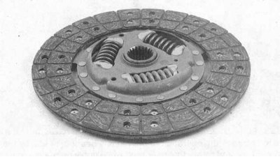
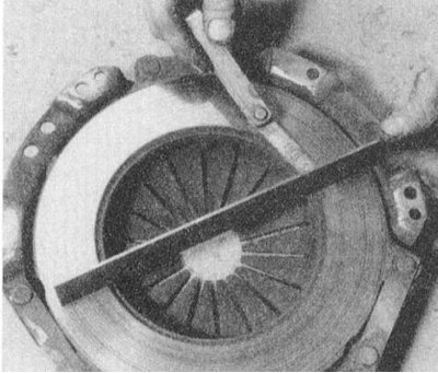
4. Assess the degree of wear of the friction linings of the clutch driven disk. The surface of the linings should rise above the heads of the rivets by at least 0.8 mm. Make sure that all rivets are firmly seated, check the torsion springs / dampers for cracks, signs of deformation and other mechanical damage. As mentioned above, it is reasonable to replace clutch components every time the assembly is dismantled, so pay attention to the slightest errors.
5. Together with the driven disk, the release bearing is also always replaced.
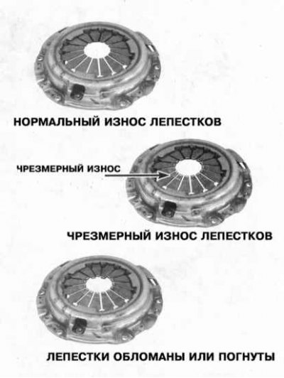
6. Assess the condition of the machined surfaces of the pressure plate and diaphragm spring petals. If defects are found, replace the basket assembly. Light polishing marks can be removed with fine sandpaper. A remanufactured clutch assembly is always available through Mitsubishi Authorized Service Stations on an exchange basis.
 |  |
Installation
1. Install the spherical support of the clutch release fork on your regular one and tighten it with the required force (35 Nm).
2. Install the clutch release fork.
3. Lubricate the bearing and contact surfaces of the fork with multipurpose grease.
4. If equipped with the same grease, lubricate the pusher of the clutch slave cylinder and its receptacle in the release fork.
5. Pack high-temperature grease into the inner groove of the release bearing, being careful not to get grease on the non-metallic parts of the assembly.
6. Install the bearing in its regular place and secure it with a retainer.
7. Before installation, wipe the machined surfaces of the flywheel and pressure plate with a rag soaked in acetone. It is extremely important to achieve complete degreasing of the working surfaces of the components, as well as the friction linings of the driven disk. Only touch the components with clean, washed hands.
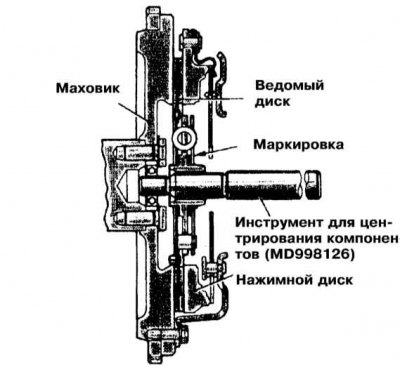
8. Press the basket assembly (with nested and fixed tool for centering components) to the flywheel. Make sure that the clutch disc is turned to the flywheel marked with the appropriate marking (type "Flywheel side") side. If there is no marking, remember that the driven disc is always installed with torsion springs / dampers to the gearbox.
9. Tighten the bolts securing the assembly to the flywheel by hand - before screwing in, the threaded part of the fastener should be lubricated with a fixing sealant.
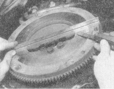
10. Center the clutch assembly components. A special tool is threaded through the hub of the driven disk and refueled into the guide bearing at the end of the crankshaft trunnion. To align the components, move the tool in different directions in the vertical and horizontal planes.
11. Tighten the assembly mounting bolts firmly in a diagonal pattern in several stages, then tighten them to the required torque (19 Nm: Galant models 1994÷1998 issue and 22 Nm: other models). Remove the clutch centering tool.
12. Establish a transmission and all components removed for the purpose of providing access. Make sure all fasteners are tightened to the correct torque.
13. Check up serviceability of functioning of coupling.