



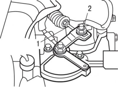
Fig. 12.18. Installing the selector cable from the automatic transmission side: 1 – gearbox control cable; 2 – nut
Selector lever for models produced since 1995
Disassembly
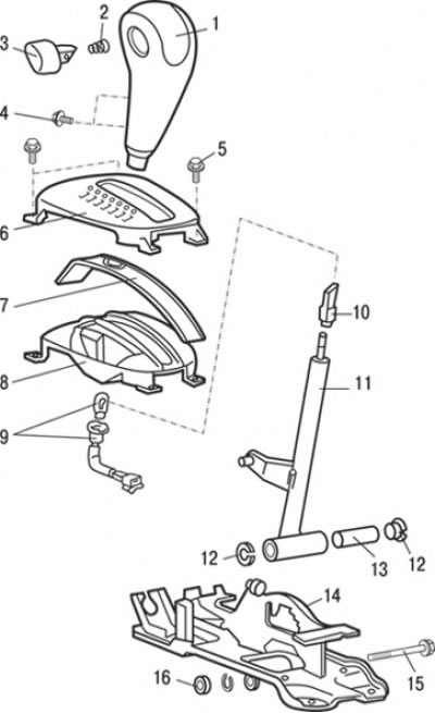
Fig. 12.19. Selector lever for models produced since 1995: 1 – selector lever handle; 2 – spring; 3 – selector lever handle button; 4 – screw (2 Nm); 5 – screw (1.5 Nm); 6 – top panel; 7 – sleds; 8 – bottom panel; 9 – selector lever position indicator light; 10 – slider; 11 – automatic transmission selector lever assembly; 12 – insert; 13 – bushing; 14 – bracket assembly; 15 – bolt; 16 – nut (12 Nm)
1. Remove the socket with the illumination lamp 9 (Fig. 12.19) for indicating the position of the selector lever.
2. Loosen screws 4 and remove the selector lever handle.
3. Remove the selector lever handle button 3 and spring 2.
4. Loosen the screws and remove the top panel 6, runners 7 and bottom panel 8.
5. Unscrew slider 10.
6. Unscrew bolt 15 and remove selector lever 11, insert 12 and bushing 13.
Assembly
Assembly is carried out in the reverse order of disassembly, taking into account the following.
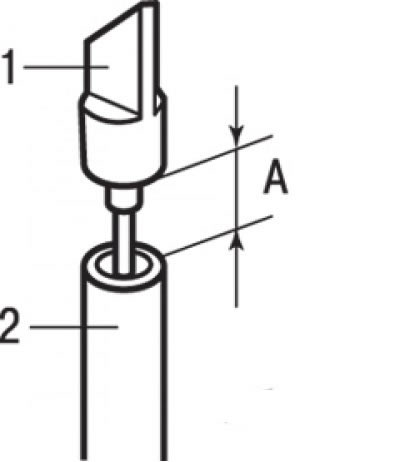
Fig. 12.20. Installing the slider on the selector lever: A – 21 mm; 1 – slider; 2 – selector lever
Set the selector lever to position "N". Rotate the slider until it is positioned at a distance "A" equal to 21 mm from the edge of the selector lever (Fig. 12.20).
Selector lever for models produced since 1999
Disassembly
1. Loosen the screw and remove the selector lever handle.
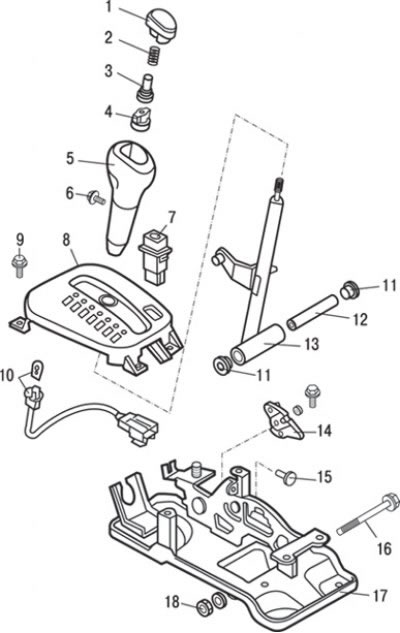
Fig. 12.21. Selector lever for models produced since 1999: 1 – button; 2 – spring; 3 – bushing; 4 – regulator; 5 – selector lever handle; 6 – screw (2.0 Nm); 7 – gearbox operating mode switch; 8 – control panel assembly; 9 – screw (1.5 Nm); 10 – selector lever position indicator lamp assembly; 11 – bushing; 12 – tube; 13 – automatic transmission selector lever assembly; 14 – cam of the selector lever locking mechanism; 15 – limiter; 16 – bolt; 17 – bracket assembly; 18 – bolt (12 Nm)
2. Remove button 1 (Fig. 12.21), spring 2, sleeve 3 and regulator 4.
3. Loosen the screws and remove the control panel 8 as an assembly.
4. Remove the 7-mode switch.
5. Remove the cotter pin, washer and remove cam 14 of the selector lever locking mechanism.
6. Unscrew bolt 16 and remove selector lever 13, bushing 11 and tube 12.
7. Unscrew limiter 15.
8. Remove the socket with the backlight lamp 10 indicating the position of the selector lever.
Assembly
Assembly is carried out in the reverse order of disassembly.