



Contents: Removal ⤓ The cable connecting the selector…⤓ Selector lever ⤓ Gearbox mode selection switch ⤓ Full Throttle Position Sensor ⤓ Installation ⤓
Removal
To remove, follow these steps in sequence.
1. Remove the air filter assembly.
2. Remove the floor console.
Caution: When removing and installing the cable connecting the selector lever to the control valve block, be careful and gentle so as not to hit any of the SRS system components.
The cable connecting the selector lever to the control valve block
1. Remove the air filter assembly.
2. Remove the battery and battery tray.
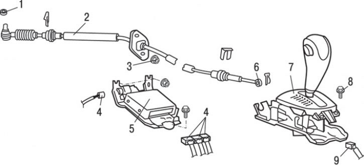
Fig. 12.14. Elements of the automatic transmission control mechanism: 1, 3 – nuts (13 Nm); 2 – gearbox control cable; 4 – connector; 5 – gearbox control unit and bracket assembly; 6 – gearbox control cable tip; 7 – selector lever assembly; 8 – bolt (12 Nm); 9 – connector
3. Disconnect electrical connectors 4 from the automatic transmission control unit (Fig. 12.14).
4. Unscrew the bolts and remove the automatic transmission control unit 5 and the bracket assembly.
5. Loosen nut 1 and disconnect the control cable from the automatic transmission.
6. Disconnect the automatic transmission control cable from the selector lever 7.
7. Loosen the flange mounting nuts and remove gearbox control cable 2.
Selector lever
1. Remove cable 6 (see Fig. 12.14) of the gearbox control assembly.
2. Disconnect electrical connector 9.
3. Unscrew the bolts and remove the selector lever 7 as an assembly.
Gearbox mode selection switch
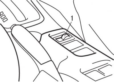
Fig. 12.15. Location of the gearbox operating mode selection switch (1)
Using a screwdriver blade as a lever, remove the gearbox mode selection switch 1 (Fig. 12.15) and disconnect the electrical connector from it.
Full Throttle Position Sensor
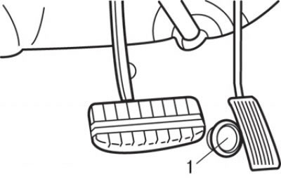
Fig. 12.16. Location of the full throttle opening sensor (1)
Using a screwdriver blade as a lever, remove the full throttle position sensor 1 (Fig. 12.16).
Installation
Installation is carried out in the reverse order of removal, taking into account the following.
1. Set the gear selector lever to the "N" position.
2. Make sure the starter lock switch is in the "N" position.
(The original article is on the website: mitsubishiman)
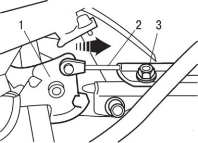
Fig. 12.17. Installing the ignition switch lock cable onto the selector lever lock mechanism cam: 1 – cam; 2 – cable; 3 – nut
3. Loosen the adjusting nut, carefully pull the cable connecting the selector lever to the control valve block in the direction of the arrow shown in Fig. 12.17, and tighten the nut.
4. Install the gearshift lock cable on the selector lever side.
5. Pre-set the selector lever handle and move the selector lever to the "P" position and turn the ignition key to the "LOCK" ("OFF") position.
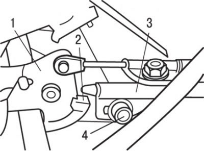
Fig. 12.6. The end of the transmission mode lock cable protrudes above the red mark on the cam when tightening the lock nut: 1 – cam of the locking mechanism; 2 – cable of the automatic transmission selector lever locking mechanism; 3 – nut; 4 – screw
6. Tighten the lock nut to 12 N·m so that the end of the gearshift lock cable protrudes above the red mark (see Fig. 12.6) on the selector lever lock cam.
7. Install the ignition switch lock cable on the selector lever side.
8. Install the ignition switch lock cable onto the selector lever lock mechanism cam.
9. Install the ignition switch lock cable spring and washer as shown in Fig. 12.17.
10. Lightly pull the part of the cable connected to the selector lever locking mechanism cam in the direction of the arrow shown in Fig. 12.17 and tighten the nut to a torque of 12 N·m.
11. Install the selector cable from the automatic transmission side.
12. Set the automatic transmission selector lever to the "N" position.
13. Make sure the starter lock switch is in the "N" position.
14. Pull the automatic transmission selector cable slightly and tighten the adjusting nut to a torque of 12 N·m.
15. Install the air filter assembly.
16. Install the floor console.