



Contents: Transmission control mechanism MA904A ⤓ The procedure for removing parts of…⤓ Procedure for removing parts of the…⤓ Removal and installation ⤓ Transmission control cable ⤓ Fixation cable ⤓ Locking cable ⤓
Transmission control mechanism MA904A
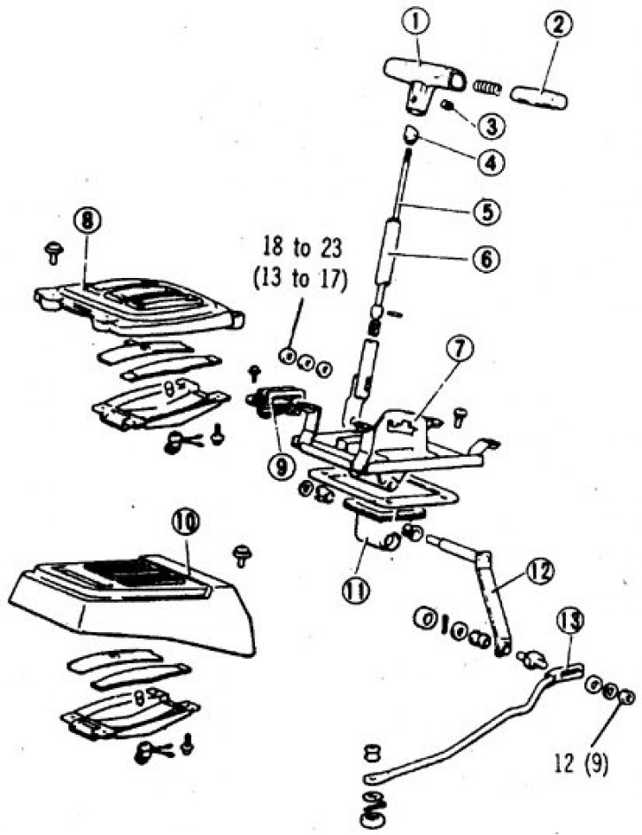
1. Handle; 2. Button; 3. Screw; 4. Eccentric; 5. Rod; 6. Selector; 7. Sector; 8, 10. Selector position indicator cover; 9. Locking switch; 11. Bracket cover; 12. Lever; 13. Traction
The procedure for removing parts of the transmission control mechanism KM 148
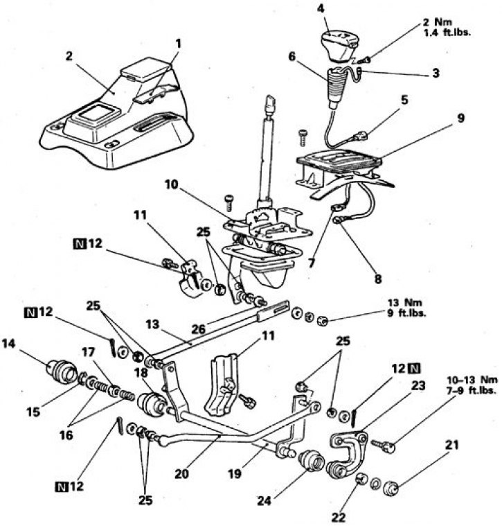
1. Plate; 2. Floor section; 3. High gear switch connector; 4. Handle; 5. High gear shifter wires and connector; 6. Cover; 7. Lock switch and front connector; 8. Selector position indicator indicator lamp wire and connector; 9. Index panel; 10. Bracket; 11. Shield; 12. Cotter pin; 13. Pull B; 14, 18, 24. Cover; 15. Retaining ring; 16. Spring; 15, 25. Bushing; 19. Transverse traction shaft; 20. Thrust A; 21. Cap; 22. Bushing; 23. Cross tie rod bracket; 26. Axis
Parts marked with N are subject to replacement.
Procedure for removing parts of the transmission control mechanism V4AW2(3)
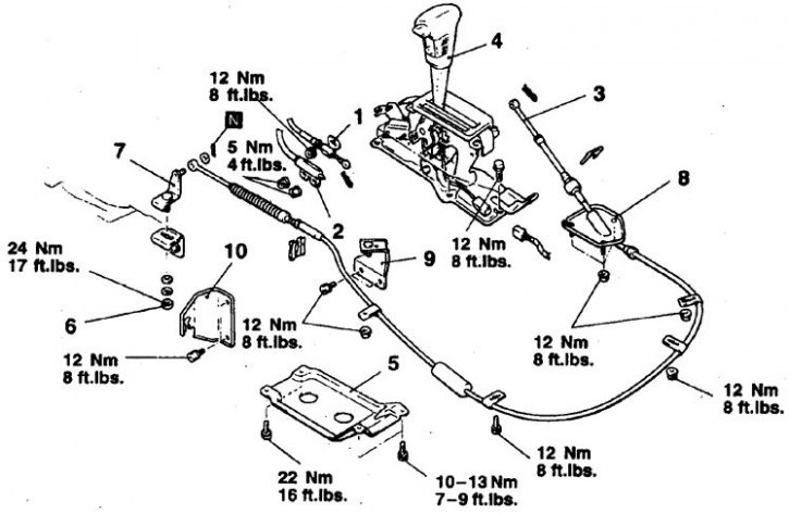
1. Fastening the locking cable (from the selector side); 2. Fastening the gear locking cable (from the selector side); 3. Fastening the transmission control cable (from the selector side); 4. Selector; 5. Transfer case shield; 6. Fastening the transmission control cable (from transmission); 7. Upper arm; 8. Cable; 9. Cable bracket; 10. Cable and bracket
Parts marked with N are subject to replacement.
Removal and installation
Attention! Some work is performed under the vehicle.
Cars 1983-86.
1. Disconnect the battery from ground.
2. Remove the selector handle.
3. Remove the center section and the selector position indicator.
4. Disconnect the indicator lamp and switch connector.
5. Disconnect the rod from the lever by unscrewing the nut while working under the vehicle.
6. Loosen the screws and remove the bracket.
7. Assembly is carried out in reverse order, taking into account the following.
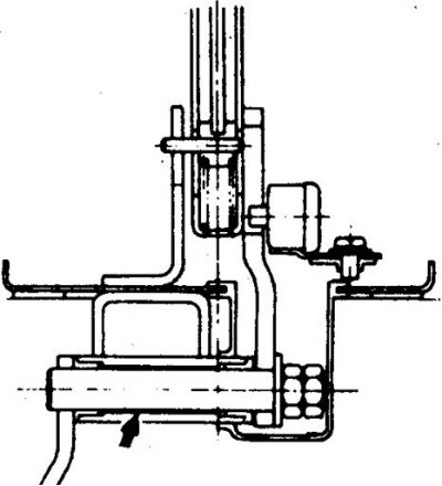
8. Lubricate the rubbing parts of the lever and rod with SAE J310A or NLGI N3 grease.
9. Adjust the position of the locking switch (see subsection 9.3.2.1).
10. If the rod was removed from the lever, set the selector to neutral, then move the rod, setting the transmission to neutral (block the wheels).
11. Make sure that the starter only engages in positions P and N and when the reverse signal is triggered in position R.
12. Adjust the selector eccentric. To do this, rotate the eccentric, set the distance between the ends of the selector and the eccentric to 11.3–12.7 mm.
Cars 1987-89.
1. Disconnect the battery from ground.
2. Move the boot down and disconnect the overdrive switch connector on the handle.
3. Loosen the screws and remove the handle, disconnect the upper switch connector, remove the cover.
4. Remove the selector position indicator by unscrewing the cover screws and disconnecting the connectors of the locking switch and indicator lamp.
5. Remove the bracket with the control mechanism.
6. To do this, working from below, unscrew the nuts, disconnect rod B from the lever, the transverse rod from rod B, remove the washers and shield.
7. Remove the boot, remove the retaining ring, springs, bushings and the transverse tie rod seal.
8. Unscrew the bolts of the brackets on the transfer case, remove the cotter pin and disconnect the cross rod from rods A and B, remove the bushings and washers.
9. Remove the tie rod shaft.
10. Unpin and disconnect rod A, remove bushings and washer.
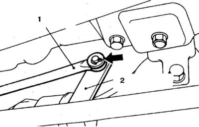
11. Replace the cotter pins of the rod connections (1 – rod A, 2 – transverse rod shaft).
12. Assembly is carried out in reverse order, taking into account the following.
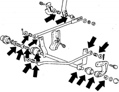
13. Lubricate the indicated areas with SAE J310A or NLGI N3 grease.
14. Replace all parts indicated.
15. Set the B rod by moving the selector and transmission to neutral position.
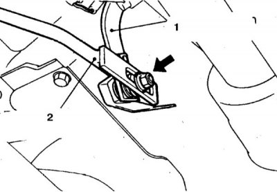
16. Make sure that the bushings and washers of rod B are installed correctly (1 – lever, 2 – rod B).
17. Tighten all connections to the required torques.
18. Check the operation of the transmission control mechanism and the engagement of the highest gear when pressing the button on the handle.
Cars 1990-98.
1. Disconnect the battery from ground.
2. Disconnect all cables from the selector.
3. Loosen the bolts and remove the selector assembly.
4. Loosen the bolts and remove the transfer case shield.
5. Loosen the nut securing the upper arm to the bracket on the transmission.
6. Remove the cotter pin and disconnect the cable from the lever.
7. Unscrew the nuts and bolts securing the brackets (6–8 pcs.) and remove the cable and cable end brackets.
8. Remove the cable.
9. Assembly is carried out in reverse order, taking into account the following.
10. Lubricate the rubbing points (axles).
11. Tighten all connections to the torques shown in the illustration.
12. Adjust the cables in the following order.
Transmission control cable
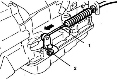
13. Move the selector to position N, work under the vehicle, loosen the lock nut, slightly feed the cable (2) towards the front of the transmission and tighten the nut (1).
Fixation cable
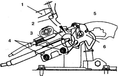
14. Move the selector to position P and adjust the position of the cable so that the red mark (end of the cable) was in the specified position, tighten the nut (1, 3 - cable, 2 - lock stop, 4 - nut, 5 - lock cam, 6 - location of the end of the cable).
Locking cable
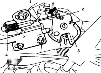
15. Put on the spring (the selector is in position P) and the washer in a certain way (1 – cable, 2 – axle, 3 – locking cam, 4 – washer, 5 – spring).
16. Slightly push the cam in the direction of the arrow until it stops and tighten the nut.