



Contents: Rod mechanism ⤓ Mechanism with cables ⤓
Rod mechanism
1. Disconnect the gear shift lever (if necessary), remove the center panel.
2. On Precis models so equipped, remove the rear floor heating duct.
3. On Mirage and Cordia/Tredia models, remove the gearshift bracket mounting nuts.
4. Raise the vehicle and place it on stable stands.
5. Unscrew the bolt and disconnect the extension rod from the gearbox (see illustration).
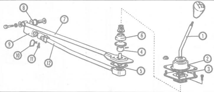
2.5a. Details of the gear shift mechanism of the Cordia/Tredia manual transmission. 1. Gear shift lever, 2. Boot, 3. Insulator, 4. Ball bushing, 8. Dust boot, 6. Rubber insulator, 7. Extension rod, 8. Bushing, 9. Dust boot, 10. Lock wire, 11. Set screw, 12. Gear shift rod.
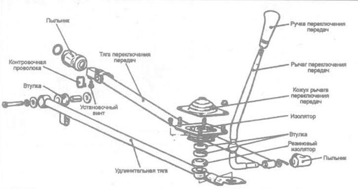
2.5b. Shift mechanism parts with rod - Mirage and Precis models.
6. Remove the safety wire from the shift rod set screw. Loosen (Cordia/Tredia models) or unscrew (Mirage and Precis models) the set screw and disconnect the shift rod from the transmission.
7. On some Cordia/Tredia models, remove the heat shield from the body to provide clearance for removal of the shift mechanism.
8. Disconnect the extension rod and gear shift lever assembly by lowering them from the vehicle.
9. Install in reverse order. These models are not adjustable.
Mechanism with cables
Removal
10. Remove the gear shift knob and center panel.
11. Check that the gearshift lever and the gearshift and selector cable levers are in the neutral position. Remove the cotter pins and clips and disconnect the gearshift cables from the gearshift lever (see illustration).
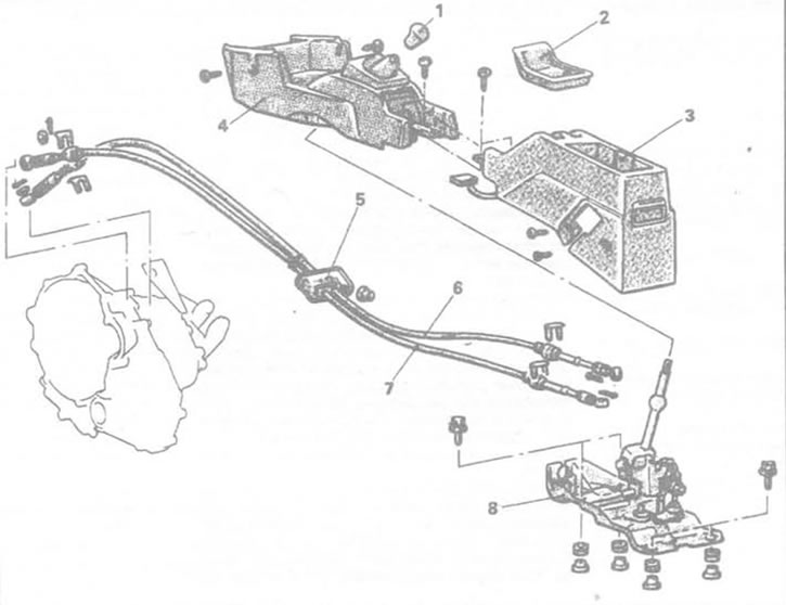
2.11a. Shift mechanism parts with cables - Mirage and Precis models. 1. Shift knob, 2. Center console tray, 3. Rear console, 4. Center console, 5. Cable holder, 6. Shift cable, 7. Selector cable, 8. Shift lever assembly.
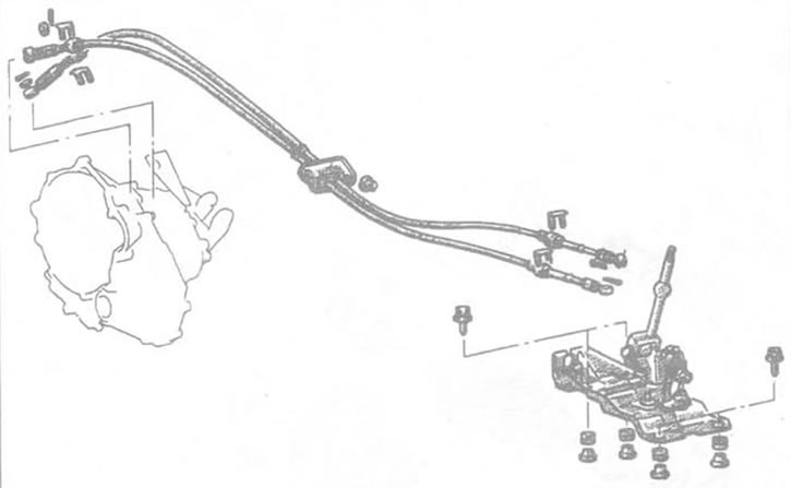
2.11b. Gear shift mechanism parts with cables - Galant model.
12. Unscrew the bolts or nuts and disconnect the cable holders.
13. In the engine compartment, remove the cotter pins and clamps, then disconnect the cables from the gearbox.
14. Pull the cables into the passenger compartment.
Installation
15. With the gearshift lever and the gearshift and selector levers in neutral, connect the cables to the gearshift lever assembly (see illustration). If necessary, turn the adjusters located on the cable on the gearshift lever side to set lever 8 to neutral (see illustration).
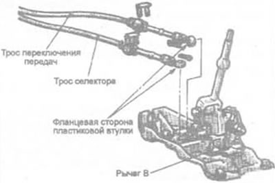
2.15a. Elements of connecting the cable to the gear shift lever - lever B must be in neutral.
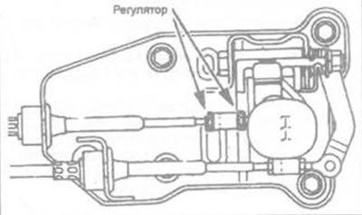
2.15b. Adjust the length of the cable by turning the nut (marked "Adjuster").
16. Connect the cables to the gearbox and install the holders.
17. After installation, dimensions A and B on both sides of the gear shift lever should be equal (see illustration). If not, adjust the cable.
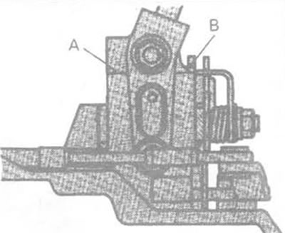
2.17. Dimensions A and B on both sides of the gear shift lever must be equal.