



Cars with F5MR1 and F5MR2 gearboxes
Removal
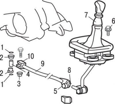
Fig. 11.7. Gear shift mechanism of the F5MR1 and F5MR2 gearbox: 1 – O-ring gasket; 2 – gear shift rod bushing; 3 – nut (16 Nm); 4 – sleeve; 5 – connection of gear shift rod assembly (from gear shift lever side); 6 – bolt (25 Nm); 7 – gear shift lever assembly; 8 – gear shift rod adjusting bolt (24 Nm); 9 – gear shift rod assembly; 10 – gear shift rod assembly connection (gearbox side)
1. Loosen the adjusting bolt 8 (Fig. 11.7) of the gear shift rod.
2. Loosen the nut and remove the bolt securing the gear shift rod 5 from the gear shift lever side.
3. Hang the gear shift rod assembly from below to the vehicle's transmission components using wire.
4. Unscrew the nut and remove the bolt securing the gearshift rod 10 from the gearbox side.
5. Remove the O-rings 1, the gearshift rod bushings 2 and the sleeve 4.
6. If necessary, remove the gear shift lever 7 as an assembly.
Installation
Installation is carried out in the reverse order of removal, taking into account the following.
1. Check the operation of the reverse gear lock.
2. Check the operation of the gear shift lever.
Cars with F5M42 and F5MV1 gearboxes
Caution: When removing and installing the gear shift lever and gear shift cables, be careful not to subject the SRS electronic control unit to impacts.
Removal
1. Remove the air filter assembly.
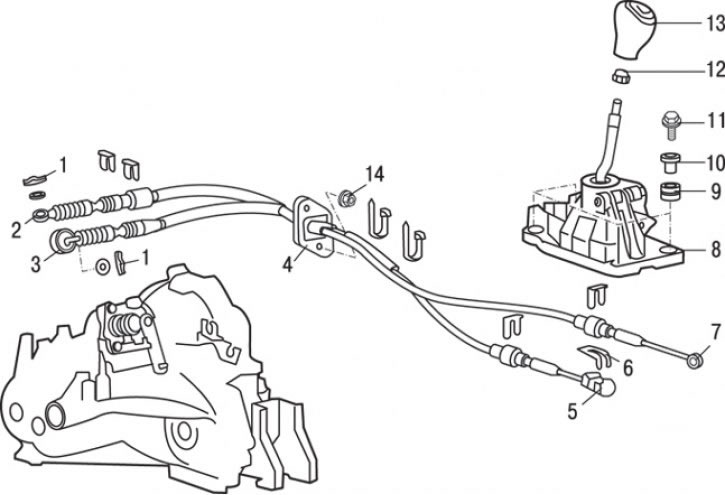
Fig. 11.8. F5M42 gearbox control mechanism: 1 – cotter pin; 2 – gear selection cable connection (from the gearbox side); 3 – gear shift cable connection (from the gearbox side); 4 – shift cables and gear selection cable assembly; 5 – gear shift cable connection (from the passenger compartment side); 6 – retainer; 7 – gear selection cable connection (from the passenger compartment side); 8 – gear shift lever assembly; 9 – bushing; 10 – spacer sleeve; 11 – bolt (25 Nm); 12 – bushing; 13 – gear shift lever handle; 14 – nut (12 Nm)
2. Pull up and remove the handle of the gear shift lever 13 (Fig. 11.8).
The source of the article is available at [MitsubishiMan.ru]
3. Remove bushing 12.
4. Remove the front floor console assembly.
5. Disconnect the gear selection cable 7 from the gear shift lever (from the passenger compartment side).
6. Remove retainer 6 and disconnect gear shift cable 5 (from the passenger compartment side).
7. Remove cotter pins 1, disconnect (from the gearbox side) gear selection cable 2 and gear shift cable 3 and remove them.
Installation
Installation is carried out in the reverse order of removal, taking into account the following.
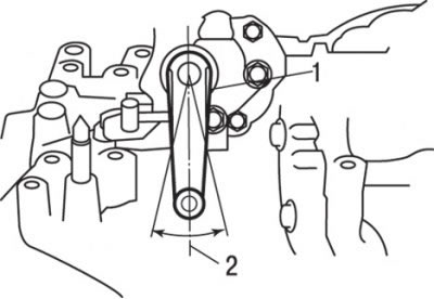
Fig. 11.9. Setting the gearshift lever on the gearbox to the neutral position: 1 – gear shift lever; 2 – neutral position
1. Set the gearshift lever on the gearbox and the gearshift lever in the passenger compartment to neutral position (Fig. 11.9).
2. On the gearbox side, identify the ends of the gear shift and gear selection cables using the white and yellow marks and secure them using cotter pins.
3. Move the gear shift lever to all operating positions and check its functionality: shifting should be smooth and without sticking.