



Contents: Removal ⤓ Installation ⤓
Removal
1. Drain the oil from the gearbox.
2. Remove the lower protective cover.
3. Remove the air filter assembly.
4. Remove the battery and its tray.
5. Remove the fuel vapor canister.
6. Remove the gear shift rods as an assembly.
7. Remove the charge air cooler air duct (1997 and later models).
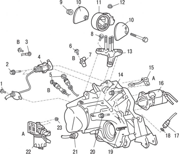
Fig. 11.13. Gearbox fastening elements: A - only gearbox F5MR3; B – only gearbox F5MV1; 1 – nut (48 Nm); 2 – bolt (30 Nm); 3 – ground wire; 4 – clutch slave cylinder; 5 – gearbox control cables (F5MV1); 6 – bolt (10 Nm); 7 – engine crankshaft position sensor (F5MV1); 8 – bolt (56 Nm); 9 – nut (118 Nm); 10 – gearbox locking flange; 11 – gearbox support bracket; 12 – nut (62 Nm); 13 – lower gearbox support bracket; 14 – Upper gearbox mounting bolts (50 Nm); 15 – vehicle speed sensor (F5MR3); 16 – starter; 17 – speedometer cable connection; 18 – O-ring sealing gasket; 19 – cotter pin; 20 – bolt (49 Nm); 21 – Reverse light switch connector; 22 – Fuel filter assembly (F5MR3); 23 – nut (25 Nm)
8. Remove cotter pin 19 (Fig. 11.13), disconnect speedometer drive cable 17 from the gearbox and remove ring seal 18.
9. Disconnect electrical connector 21 of the reversing light switch.
10. Disconnect the gearbox control cables 5 (gearbox F5MV1).
11. Loosen the bolt and disconnect the ground wire 3 (gearbox F5MV1).
12. Loosen the bolt and remove the engine crankshaft position sensor 7 (gearbox F5MV1).
13. Unscrew the bolts, remove the starter 16 together with the wires attached to it and secure it inside the engine compartment.
14. Remove the 4th clutch slave cylinder without disconnecting the hydraulic tubes and hoses, and tie it to the vehicle chassis.
15. Disconnect the vehicle speed sensor electrical connector (F5MR3 transmission).
16. Unscrew the upper connecting bolts 14 of the gearbox assembly.
17. Remove the bolts and disconnect the fuel filter assembly from the vehicle body, but do not disconnect the fuel hoses from it (F5MR3 transmission).
18. Carefully lift the gearbox with a hydraulic jack, then unscrew the nut, remove the bolt, remove the gearbox locking flanges and disconnect the gearbox support bracket 11.
19. Install a special tool (engine lift with hand hoist and crossbar) on the vehicle to support the engine.
20. Unscrew the bolts securing the lower bracket 13 of the gearbox support.
21. Raise the car on a lift.
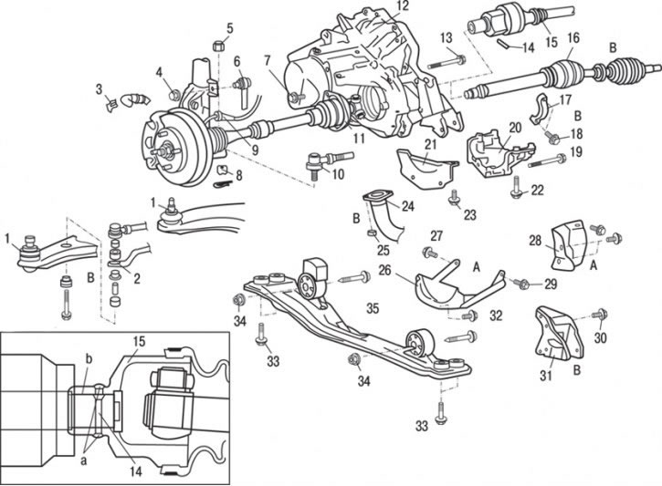
Fig. 11.14. Fastening elements of F5MR1 and F5MR2 gearboxes: A - only gearbox F5MR3; B – only gearbox F5MV1; a – place of application of lubricant; b – place of sealant application; 1 – connection of the ball joint pin of the lower suspension arm with the steering knuckle; 2 – anti-roll bar; 3 – brake hose retainer; 4 – nut (44 Nm); 5 – nut (59–71 N·m); 6 – anti-roll bar connection; 7 – bolt (25 Nm); 8 – nut (15–33 Nm); 9 – Wheel speed sensor connector (cars with ABS); 10 – connection of the ball joint pin of the steering rod end with the steering knuckle; 11 – left wheel drive shaft connection; 12 – gearbox assembly; 13 – lower gearbox connecting bolts (50 Nm); 14 – split pin; 15 – left wheel drive shaft connection; 16 – right wheel drive shaft connection; 17 – bearing bracket; 18 – bolt (25 Nm); 19 – bolt (48 Nm); 20 – Gearbox mounting bracket (SOHC engine); 21 – Front clutch housing cover (SOHC engine); 22 – bolt (22–25 Nm); 23 – bolt (10–12 Nm); 24 – exhaust inlet pipe; 25 – bolt (25 Nm); 26 – curved strut; 27 – bolt (40 Nm); 28 – heat protection; 29 – bolt (39 Nm); 30 – bolt (50 Nm); 31 – rear support of the power unit; 32 – bolt (22 Nm); 33 – bolt (69 Nm); 34 – bolt (59 Nm); 35 – longitudinal beam assembly
22. Loosen the nuts and disconnect the anti-roll bar links 6 (Fig. 11.14).
23. Remove the brake hose fastening clip 3.
24. Disconnect connector 9 of the wheel speed sensor (vehicles with ABS).
25. Using a special tool, loosen the ball joint pin mounting nut and, using a puller, disconnect the steering rod end from the steering knuckle, then completely unscrew the nut.
Caution: To prevent the puller from bouncing, hang it on a wire or cord.
26. Using a special tool, loosen the nut 1 of the ball joint pin of the lower suspension arm and, using a puller, disconnect the lower suspension arm from the steering knuckle, then completely unscrew the nut.
27. Loosen the nuts and remove the anti-roll bar 2 (gearbox F5MV1).
28. Loosen the bolts and remove the longitudinal beam 35 as an assembly.
29. Disconnect the wheel drive shaft together with the hub and steering knuckle.
30. Loosen the bolts and remove the heat shield (F5MR3 gearbox).
31. Hang the removed wheel drive shaft inside the wheel arch using wire so as not to allow strong bending in the CV joints.
32. Remove the sealant and, using a punch, knock out the split pin 14.
33. Disconnect drive shaft 15 together with the hub and steering knuckle.
34. Hang the removed wheel drive shaft inside the wheel arch using wire so as to prevent strong bending in the CV joints.
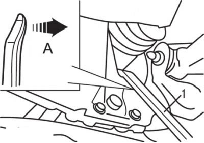
Fig. 11.15. Removing the right wheel drive shaft: A – location of the gearbox; 1 – mount
35. To disconnect the drive shaft, insert a pry bar between the gearbox housing and the shaft as shown in Fig. 11.15 (F5MV1 gearbox).
Caution! Do not disconnect the drive shaft from the steering knuckle and hub. Always use a pry bar, otherwise the CV joint tripod (TJ) of the drive shaft will be damaged
36. Suspend the removed wheel drive shaft with a wire so as to prevent severe bending in the CV joints (F5MV1 gearbox).
37. Cover the gearbox with a rag to prevent foreign particles and objects from getting inside the gearbox.
38. Carefully raise the gearbox with a hydraulic jack and remove the gearbox support bracket (F5MV1 gearbox).
39. Loosen the bolts and remove the bracket mounting bolts 17 (see Fig. 11.14) (gearbox F5MV1).
40. Loosen the nuts and disconnect the exhaust inlet pipe 24 (gearbox F5MV1).
41. Loosen the bolts and remove the curved spacer (F5MR3 gearbox).
42. Loosen the bolts and remove the rear support 31 of the power unit (gearbox F5MV1).
43. Loosen the bolts and remove the 20 gearbox mounting bracket (SOHC engine).
44. Loosen the bolts and remove the front cover 21 of the clutch housing (SOHC engine).
45. Unscrew the lower connecting bolts 13 of the gearbox.
46. Remove gearbox 12 as an assembly.
Installation
Installation is carried out in the reverse order of removal, taking into account the following.
1. After applying multi-purpose grease to the splined portion of the drive shaft, align the split pin hole on the end of the shaft with the split pin hole on the end of the shaft on the transmission side, and then install the drive shaft.
2. If the split pin hole is slightly misaligned, rotate the drive shaft 180° and then try to install it again.
Caution: Due to the fact that the drive shaft has an odd number of splines, the pin hole will be offset by half a diameter if the shaft is rotated 180°.
3. Apply Mitsubishi genuine part MD970389 or equivalent sealant to the split pin and then insert it into the drive shaft.
4. After installing the pin, apply sealant to both sides of the pin hole to completely seal them.
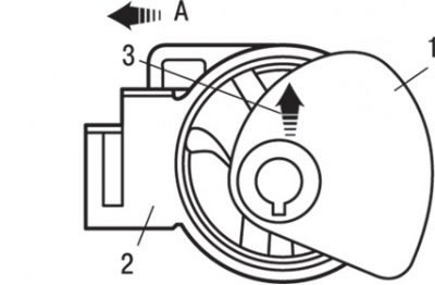
Fig. 11.16. Installing the gearbox locking flange: A – engine location; 1 – transmission support stopper; 2 – transmission support bracket; 3 – arrow
5. Install the gearbox support limiter so that the arrow on the flange points in the direction shown in Fig. 11.16.
[The original article is on: MITSUBISHIMAN]
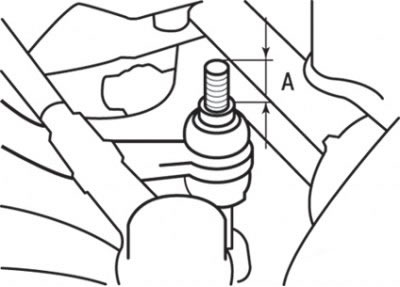
Fig. 11.17. Stabilizer mounting bolt protrusion distance: A = 22 mm
6. Tighten the self-locking nut so that the stabilizer mounting bolt protrudes above the nut as shown in Fig. 11.17 (F5MV1 gearbox).
7. Install the gear shift rod assembly.
8. Install the adsorber.
9. Install the battery.
10. Install the air filter assembly.
11. Install the lower protective cover.
12. Fill with transmission oil.
13. Check the operation of the gear shift lever.
14. Check the operation of the speedometer.