



Contents: Removal ⤓ Installation ⤓
Removal
1. Drain the working fluid from the gearbox.
2. Remove the lower protective cover.
3. Remove the air filter assembly.
4. Remove the battery and its tray.
5. Remove the fuel vapor canister.
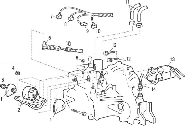
Fig. 12.22. Automatic transmission fastening elements: 1 – gearbox support stopper; 2 – gearbox support bracket; 3 – nut (118 Nm); 4 – nut (98 Nm); 5 – end of the cable connecting the gearbox selector lever to the control valve block; 6 – nut (13 Nm); 7 – electromagnetic valve block connector; 8 – Gearbox selector switch connector; 9 – speed sensor connector "B"; 10 – speed sensor connector "A"; 11 – connection of hoses of the gearbox oil cooling system; 12 – Upper gearbox mounting bolts (48 Nm); 13 – starter; 14 – Speedometer drive cable connection
6. Loosen the nut and disconnect cable 5 (Fig. 12.22) connecting the selector lever to the control valve block.
7. Loosen the clamps and disconnect the coolant system hoses.
8. Disconnect electrical connectors 10, 9, 8, 7 of the speed sensors "A" and "B", the selector switch and the electromagnetic valve block, respectively.
9. Loosen the nut and disconnect the speedometer drive cable.
10. Unscrew the bolts, remove the starter 13 together with the wires attached to it and secure it inside the engine compartment.
11. Unscrew the upper connecting bolts 12 securing the gearbox assembly.
12. Carefully lift the gearbox with a hydraulic jack, then unscrew the nut, remove the bolt, remove the gearbox stop supports and disconnect the 2 gearbox support bracket.
13. Install a special tool (engine lift with hand hoist and crossbar) on the vehicle to support the engine.
Caution! Bolts marked with an (*) must first be pre-tightened and should only be fully tightened to the specified values with the vehicle standing on the ground and unloaded.
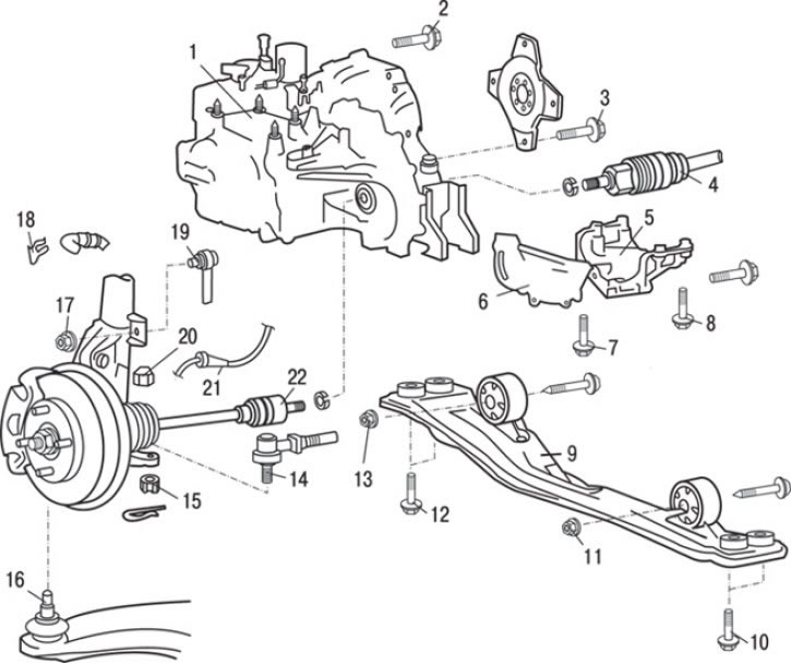
Fig. 12.23. Automatic transmission: 1 – gearbox assembly; 2 – lower gearbox mounting bolts (48 Nm); 3 – torque converter drive plate mounting bolts (45–52 Nm); 4 – right drive shaft; 5 – gearbox support; 6 – flywheel casing shield; 7 – bolt (10–12 Nm); 8 – bolt (22–25 Nm); 9 – central beam; 10 – bolt (69 Nm); 11 – bolt* (59 Nm); 12 – bolt (69 Nm); 13 – bolt* (59 Nm); 14 – Tie rod end joint; 15 – nut (15–33 Nm); 16 – ball joint of the lower suspension arm; 17 – nut (44 Nm); 18 – brake hose clamp; 19 – stabilizer connection; 20 – nut (58–71 N·m); 21 – Speed sensor connector (cars with ABS); 22 – left drive shaft
14. Loosen the nuts and disconnect the rods 19 (Fig. 12.23) of the anti-roll bar.
15. Remove the brake hose mounting bracket 18.
(The article is based on data from the website www.MitsubishiMan.ru)
16. Disconnect the connector of the wheel speed sensor 21 (vehicles with ABS).
17. Using a special tool, loosen the ball joint pin mounting nut and, using a puller, disconnect the steering rod end from the steering knuckle, then completely unscrew the nut.
Caution: To prevent the puller from bouncing, hang it on a wire or cord.
18. Using a special tool, loosen the tightening of the nut of the ball joint pin of the lower suspension arm and, using a puller, disconnect the lower suspension arm from the steering knuckle, then completely unscrew the nut.
19. Unscrew the bolts and remove the central beam 9 as an assembly.
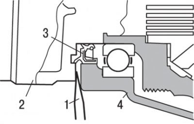
Fig. 12.24. Removing the drive shaft: 1 – mount; 2 – drive shaft; 3 – oil seal; 4 – gearbox housing
20. To remove the drive shaft, insert a pry bar between the shaft and the gearbox housing as shown in Fig. 12.24.
Caution! Do not remove the hub and steering knuckle from the drive shaft.
Caution! Always use a tire iron to avoid damaging the CV joint.
Caution: Do not insert the pry bar too deeply to avoid damaging the seal.
21. Tie the removed drive shaft with a cord so that there are no large bends in the CV joints.
22. To prevent dirt and foreign particles from entering the gearbox housing, cover the opening with a special cover.
23. Loosen the bolts and remove support 5 (see Fig. 12.23) of the gearbox.
24. Loosen the bolts and remove the flywheel housing shield 6.
25. Slightly raise the gearbox with a jack.
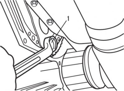
Fig. 12.25. Unscrewing the bolts (1) of the torque converter drive plate
26. Turning the engine crankshaft, unscrew the torque converter drive plate mounting bolts (Fig. 12.25).
Caution! When installing the drive shaft, be careful not to damage the working edge of the seal with the sharp edges of the splined part of the shaft.
27. Press the torque converter towards the gearbox so that it does not remain on the engine.
28. Remove the lower gearbox mounting bolts and lower it to the floor.
Installation
Installation is carried out in the reverse order of removal, taking into account the following.
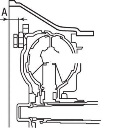
Fig. 12.26. Correct installation of the torque converter in the gearbox housing: A = 12.2 mm
1. When installing the torque converter into the gearbox housing, maintain dimension A (Fig. 12.26) and install the gearbox assembly onto the engine.
2. Temporarily install the drive shaft, ensuring that the drive shaft and the mounting hole in the gearbox housing are aligned when installing the CV joint housing.
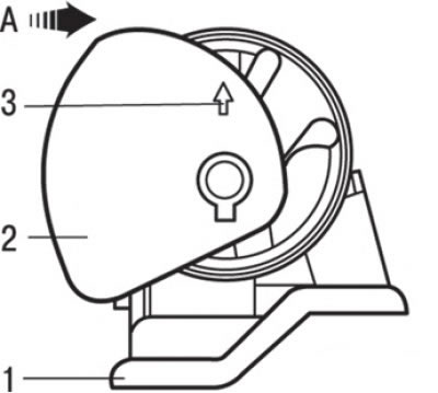
Fig. 12.27. Installing the gearbox locking flange: A – engine location; 1 – transmission support stopper; 2 – transmission support limiter; 3 – arrow
3. Install the gearbox support stop so that the arrow points as shown in Fig. 12.27.
4. Fill with working fluid.
5. Install the lower protective cover.
6. Install the fuel vapor absorber.
7. Install the battery.
8. Install the air filter assembly.
9. Check the operation of the selector lever.
10. Check the operation of the speedometer.