
Float chamber cover details (2.6 l)
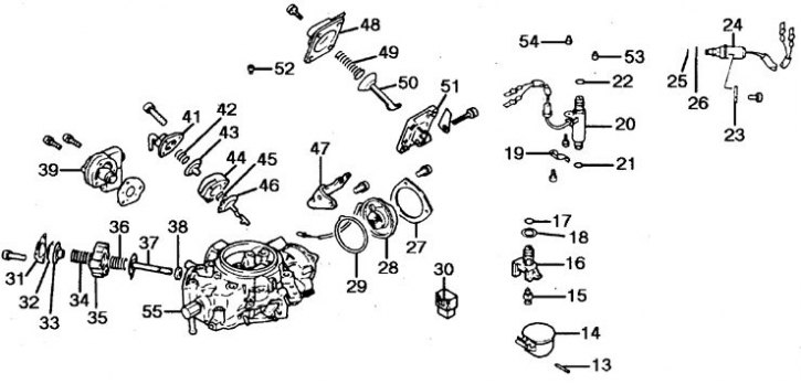
13. Axis; 14. Float; 15. Needle valve; 16. Saddle; 17, 21, 22, 25, 26. Ring; 18, 29, 40. Gasket; 19, 23. Holder; 20. FBSV valve; 24. SCSV valve; 27. Overlay; 28. Bimetallic element; 30. connector; 31, 41, 48. Cover; 32, 37, 43, 46, 50. Diaphragm; 33. Support washer; 34, 36, 42, 45, 49. Spring; 35, 44, 51. Body; 38. Valve; 39. Mixture control valve; 47. Bracket; 52. The main air jet of the primary chamber; 53. Atomizer of the primary chamber; 54. Atomizer of the secondary chamber; 55. Float chamber cover
Parts of diffusers and carburetor throttle bodies (2.6 l)
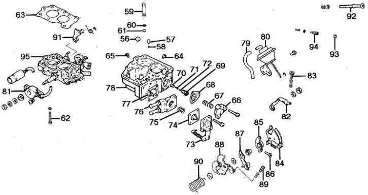
56, 58, 61, 72. Ball; 57. Counterweight; 59, 93. Plug; 60. Ring; 62. Screw; 63, 77. Gasket; 64. The main fuel jet of the primary chamber; 65. The main fuel jet of the secondary chamber; 66. Lid; 67, 71, 75, 90. Spring; 68, 74. Diaphragm; 69. Economizer valve; 70. Economizer; 73. Accelerator pump cover; 76. Pump housing; 78. Housing diffusers; 79. Hose; 80. Vacuum chamber; 81. Throttle angle sensor; 82. Lever; 83. Adjusting screw; 84. Throttle actuator lever; 85. Cam; 86. Fast idle adjustment screw; 87, 88, 91. Lever; 89. Idle adjustment screw (SAS2); 92. Idle adjustment screw (SAS1); 94. Screw for adjusting the quality of the mixture; 95. Damper body
Dismantling the carburetor
Removing Connector Pins from the Housing
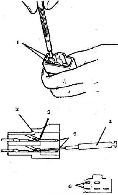
1, 6. FBSV valve terminals; 2. connector; 3. Limiter; 4. Screwdriver; 5. Conclusions
1. Remove the carburetor.
2. Remove the throttle springs.
3. Remove the coolant hose and throttle springs.
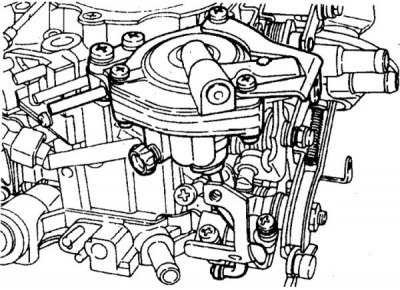
4. Remove the air shock absorber - figure on the left (on vehicles with manual transmission) or electropneumatic valve (on vehicles with automatic transmission), by unhooking the stem.
5. On vehicles with automatic transmission, unscrew the screws, remove the idle speed corrector drive and move it aside (it is forbidden to check the corrector with battery voltage).
6. Remove the connector bracket.
7. Disconnect the choke vacuum hose.
8. Remove the 5 screws and remove the float chamber cover by prying it slightly.
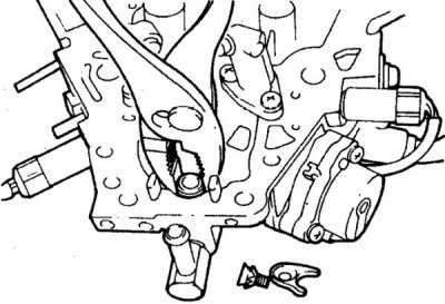
9. Remove the float, remove the needle valve and unscrew the seat.
10. Using a miniature screwdriver, disconnect the solenoid feedback valve leads (FBSV valve).
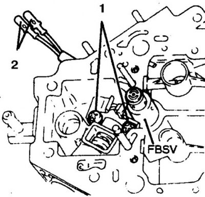
11. Remove the cover, unscrew the screw (1) and remove the FBSV valve (2 - conclusions).
12. Remove the holder and take out the solenoid shut-off valve (SCSV valve), without disconnecting wires.
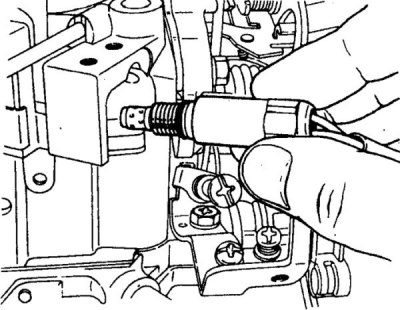
13. Use a miniature screwdriver to disconnect the wire terminals from the SCSV and remove it.
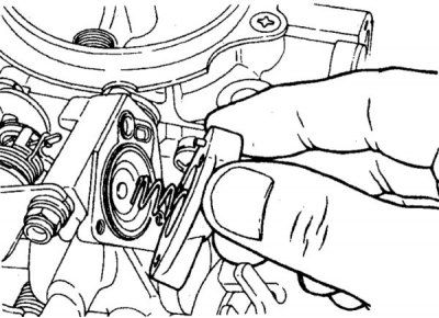
14. Remove the rivet heads and remove the choke switch cover. Loosen the small screw at the bottom of the cover.
15. Remove the gasket, bimetal element and plate.
16. Carefully remove the remains of the rivets.
17. Disconnect the output of the bimetallic element from the connector.
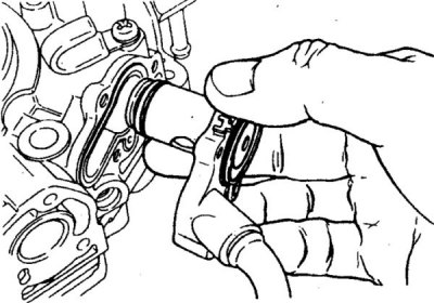
18. Remove the vent valve, paying attention to the location of the small valve springs.
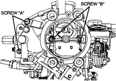
19. Remove the air damper actuator cover (the arrows indicate the air damper mounting screws).
20. Remove counterweight and check valve ball valve.
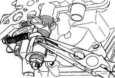
21. Disconnect the accelerator pump linkage from the throttle lever.
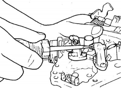
22. Carefully remove the screw from the throttle body. Turn out the main jet.
23. Turn away screws and get details of the accelerating pump from the case.
24. Loosen the 3 screws on the economizer cover and remove the cover, spring and diaphragm.
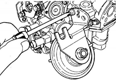
25. Disconnect the vacuum hose of the rarefaction chamber, disconnect the rod, unscrew the bolts and remove the chamber.
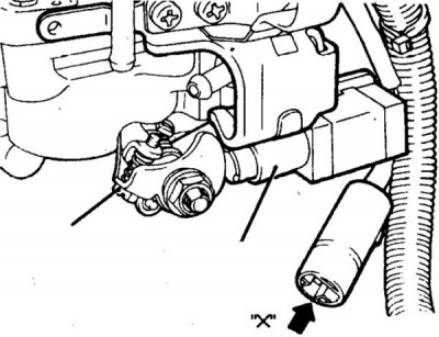
26. Remove the throttle angle sensor (indicated by an arrow).
27. Wash the carburetor passages with solvent and blow with compressed air.
28. Check the condition of the diaphragms, float and needle valve, the freedom of movement of the rods, rods and levers. Check the operation of the solenoid valves and the resistance of their windings (FBSV valve - 48-60 Ohm, SCSV valve - 54-66 Ohm, bimetal element - 6 Ohm at 20°С).
29. Check the air shock absorber by pulling the rod - resistance should be felt, when released, the rod quickly returns back.
30. Press the vacuum chamber rod and release it, closing the air suction hole with your finger - the rod should remain motionless.
Assembly
Checking choke opening at wide open throttle
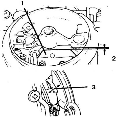
1. Air damper; 2. Clearance; 3. Lever for adjustment
1. Install the damper rotation sensor, vacuum chamber, assemble and install the economizer, accelerator pump. Install shutoff valve, air damper actuator breaker cover, vent valve. Close the main jets.
2. Assemble the bimetal connector. Install the element in reverse order, replacing the gasket and aligning the marks. Secure the cover with rivets; screws are not recommended.
3. Assemble the FBSV and SCSV valve connectors. Install the valves and assemble the damper body and diffuser body by replacing the seal and screwing in.
4. Install all parts on the float chamber cover. Adjust float position.
5. Install float chamber cover, secure with 5 screws. Install connector bracket, air spring (or pneumatic valve), all springs, levers and rods. Check up smoothness of movement of drafts.
6. Check the gap between the throttle valve and the diffuser wall by inserting a drill and moving the idle cam to its highest position. The gap should be 0.63mm on a 2.0L engine (with manual transmission), 0.71 mm on 2.0L engines (with automatic transmission), 0.71 mm on 2.6L engines (with manual transmission), 0.80 mm on 2.6L engines (with automatic transmission).
7. Check the gap between the air damper and the chamber wall at wide open throttle. To do this, close the choke with your finger and open the throttle with the lever. The gap should be 2 mm. Adjust if necessary by bending the lever.
Attention! This gap after disassembly-assembly should not change and, as a rule, is only checked. Incorrect clearance adjustment greatly impairs the driving performance of the car when the engine is cold.
8. Replace the gasket and install the carburetor (see subsection 8.1.2.1).