
WARNING: Because the automatic transmission is made up of a number of precision-manufactured parts, these parts must be handled with great care during disassembly and reassembly.
When disassembling the automatic transmission, the following conditions must be met:
- Place a rubber mat on the workbench, which must be kept clean at all times.
- During disassembly, do not use cloth gloves or rags. If necessary, use nylon products or paper napkins.
- All removed parts must be completely clean.
- Clean the clutch disk, plastic and rubber parts! using automatic transmission fluid, being careful not to leave dust, dirt, etc. on them.
Clean the surface of the gearbox.
Install the gearbox on a verst with the oil sump down.
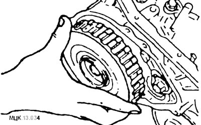
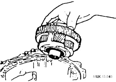
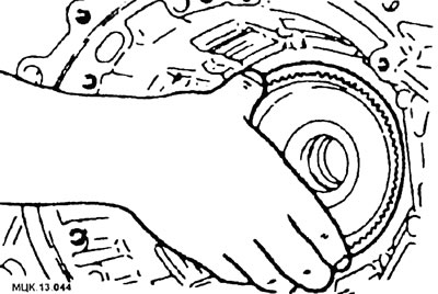
Remove the torque converter.
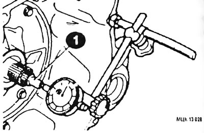
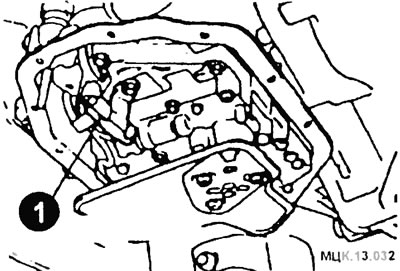
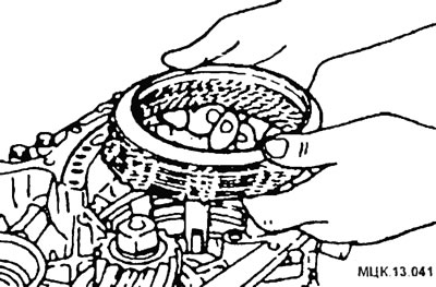
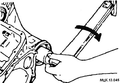
Measurement before disassembly of the axial play of the input shaft (1) usually allows you to determine if a thrust washer needs to be replaced (except when major parts are replaced).
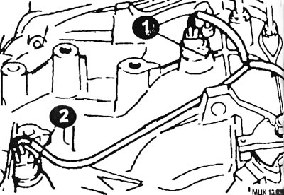
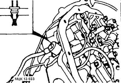
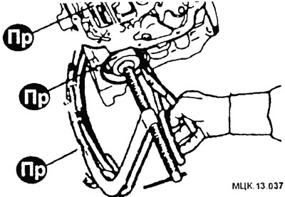
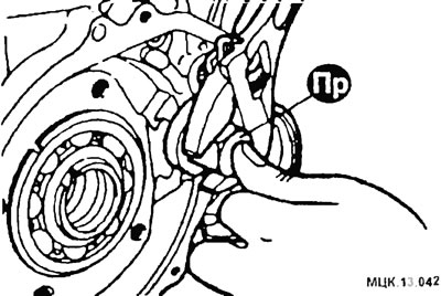
Remove pulse generators A and B (1, 2).
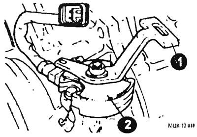
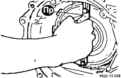
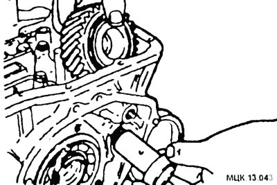
Remove the hand lever (1), then remove the gear selector (2).
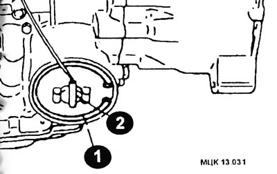
Remove snap ring (1) and servo switch (2) forced downshift (see fig.).
After removing the oil sump and its gasket, remove the oil filter from the control valve body.
Loosen the oil temperature sensor bolt (1). Push it out from the connector side.
Squeeze the tabs on the solenoid valve wiring harness o-ring and then push it into the housing.
Loosen the bolts and remove the valve body.
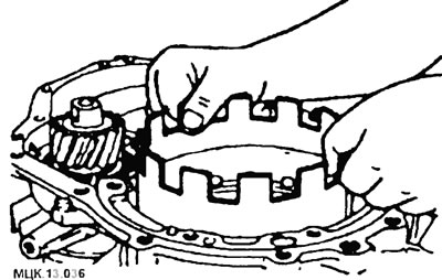
Remove the end sleeve.
Remove the end drive shaft.
Having unscrewed bolts, remove the case of the hydrotransformer.
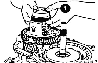
Loosen the oil pump mounting bolts. Screw the special tools into the two removable holes in the oil pump housing. Simultaneously and evenly rotate both pullers and remove the oil pump.
Remove spacer (1) and differential.
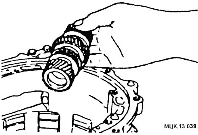
Remove by moving the input shaft up and then remove the front and rear couplings.
Remove the thrust bearing, clutch hub, thrust washer and bearing.
Remove the positive downshift servo drum.
Using the tools, slide the servo inward and remove the circlip.
Remove the piston and servo spring.
Attach the fixture to the center support. Holding the handle of the tool, pull up the center support.
Remove the reverse and forward gears together.
Remove the planet carrier and thrust bearing.
Remove the wave spring, return spring, brake disc, brake plate, brake support plate.
Using the tool, release the intermediate shaft.
Remove it and 2 gear bearing parts.
Remove the internal gear, output flange, idler gear and bearing as a unit from the housing.
Remove the transmission shaft cover.
Loosen the lock nut.
CAUTION: The lock nut has a left hand thread.
Knock out the transmission shaft towards the torque converter housing.
Using tools, remove the bearing from the transmission shaft, the bearing from the drive gear of the transmission shaft, the outer race of the transmission shaft bearing.
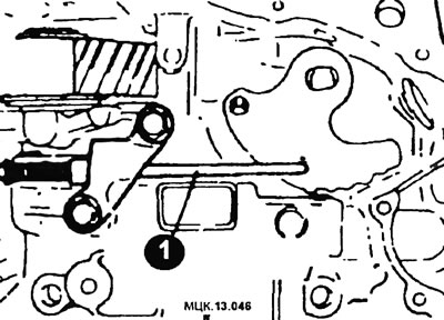
Loosen the two bolts and remove the spacer bar (1).
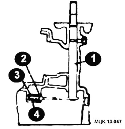
Loosen the locking screw and remove the manual control shaft (1). Remove the ball (2) nest (3) and spring (4).
ATTENTION: Further disassembly of the automatic transmission by persons who do not have experience in repairing automatic transmissions is not recommended. Below are the components of the automatic transmission in disassembled form.
Assembly
ATTENTION: Do not reuse gaskets, seals and rubber parts, replace them with new ones. Apply automatic transmission fluid to all moving parts before installation.
Assembly is carried out in the reverse order using special tools and fixtures.
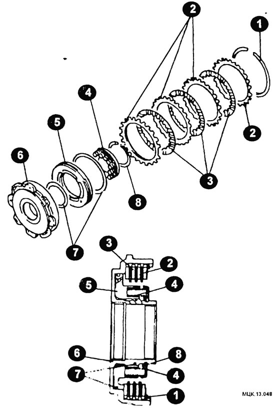
Front clutch (clutch)
1 - retaining ring; 2 - reactive plate; 3 - clutch disc; 4 - return spring; 5 - piston of the front clutch; 6 - front clutch holder; 7 - ring; 8 - retaining ring.
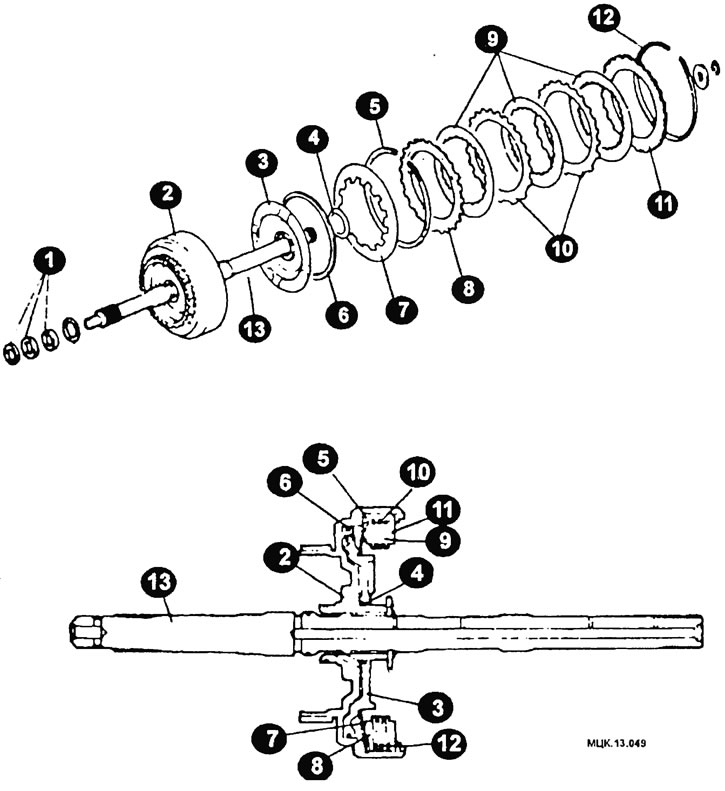
Rear clutch (clutch)
1 - seal; 2 - rear clutch holder; 3 - rear clutch piston; 4 - seal; 3 - wavy spring; 6 - seal; 7 - return spring; 8 - clutch pressure plate; 9 - clutch disc; 10 - clutch plate; 11 - reactive plate; 12 - retaining ring; 13 - input shaft.
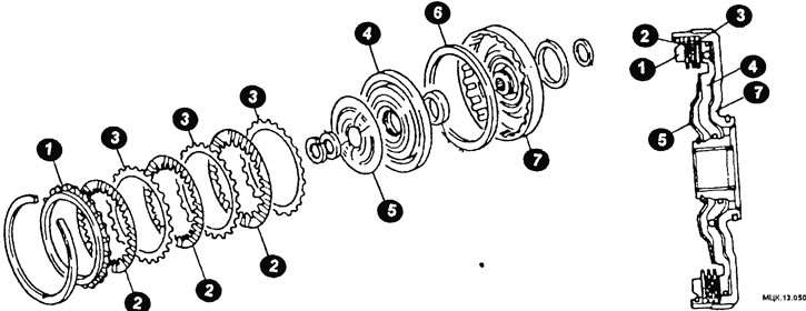
final clutch (clutch)
1 - reactive plate; 2 - clutch disk; 3 - clutch plate; 4 - piston; 3 - return spring; 6 - stuffing box; 7 - end sleeve holder.
Planetary Gear Elements
1 - satellite axis; 2 - overrunning clutch; 3 - outer ring; 4 - roller; 5 - wide satellite; 6 - support of planetary toothed knees; 7 - spacer ring; 8 - thrust bearing; 9 - narrow satellite.
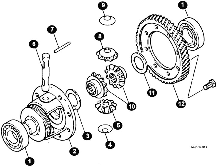
Differential elements
1 - ball bearing; 2 - differential housing; 3 - spacer washer; 4 - washer; 3 - satellite; 6 - axis of the satellites; 7 - locking pin; 8 - satellite; 9 - washer; 10 - side gears; 11 - spacer washer; 12 - drive gear.
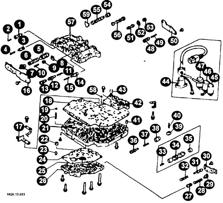
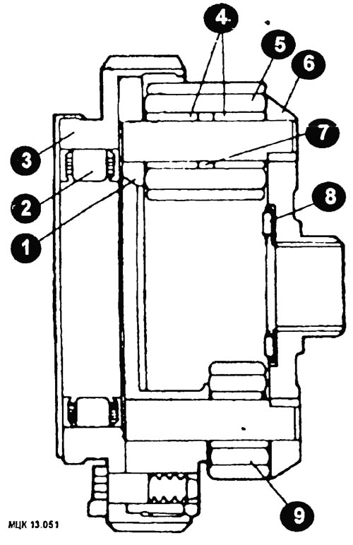
Valve body elements
1 - pressure reducing valve; 2 - pressure reducing valve spring; 3 - torque converter control valve; 4 - torque converter control valve spring; 3 - control valve; 6 - control valve spring; 7 - adjusting screw; 8 - stopper plate; 9 - switching control valve plate; 10 - spring of the switching control valve; 11 - spring of the exhaust valve of the rear clutch; 12 - exhaust valve in the rear clutch; 13 - exhaust valve A of the rear clutch; 14 - shift valve 2-3 and 3-4 gears; 15 - valve spring for shifting 2-3 and 3-4 gears; 16 - end front cover; 17 - valve stopper; 18 - upper dividing plate; 19 - steel ball; 20 - pressure reducing valve spring; 21 - intermediate plate; 22 - nut; 23 - nozzles; 24 - oil filter; 25 - lower dividing plate; 26 - lower valve body; 27 - pressure reducing valve; 28 - pressure reducing valve spring; 29 - adjusting screw; 30 - end cover; 31 - ND control valve; 32 - ND control valve spring; 33 - damping clutch control valve spring; 34 - damping clutch control valve; 35 - damping clutch control valve bushing; 36 - end sleeve valve; 37 - valve spring of the end coupling; 38 - piston of the end sleeve valve; 39 - stopper; 40 - pin; 41 - mounting sleeve; 42 - block; 43 - tube; 44 - pressure control solenoid valve; 45 - solenoid valve B for switching control; 46 - solenoid valve A for switching control; 47 - damping clutch control solenoid valve; 48 - switching valve 1-2; 49 - switching valve spring 1-2; 50 - rear end cap; 51 - switch control valve cover; 52 - locking plate; 53 - piston B of the switching control valve; 54 - ND shift control valve bushing; 55 - ND switching control valve; 56 - manual control valve; 57 - upper valve body; 58 - Teflon ball; 59 - ND shift control valve plate.
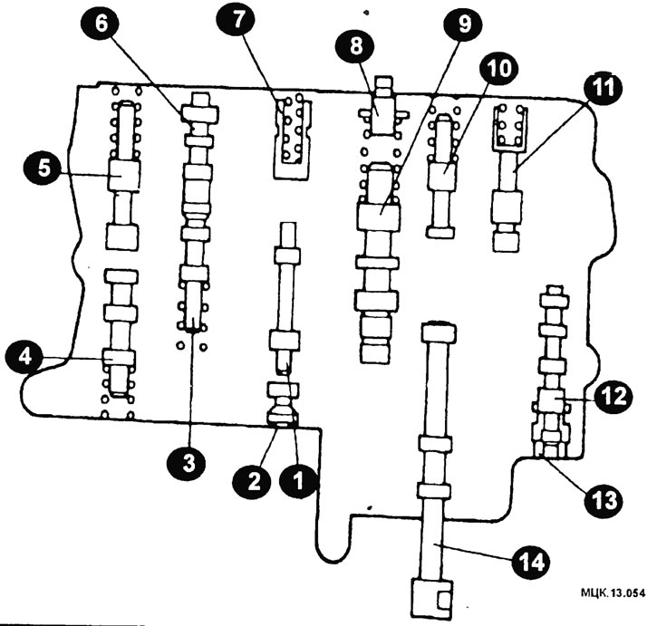
Location of valves in the upper body
1 - switching control valve; 2 - piston B of the switching control valve; 3 - piston In the exhaust valve of the rear clutch; 4 - valve for switching 1-2 gears; 3 - valve for switching 2-3 and 3-4 gears; 6 - piston A of the rear clutch exhaust valve; 7 - piston A of the switching control valve; 8 - adjusting screw; 9 - control valve; 10 - torque converter control valve; 11 - pressure control valve; 12 - ND control valve; 13 - ND control valve bushing; 14 - manual control valve.
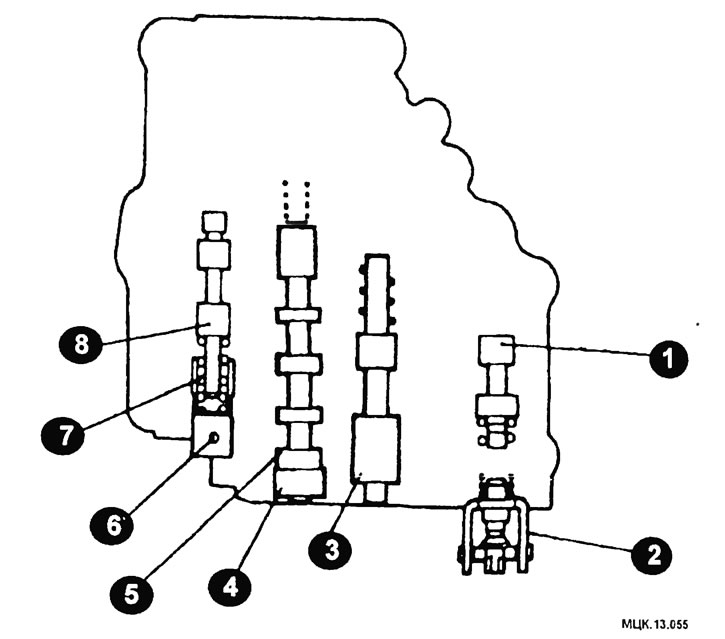
Location of valves in the lower case
1 - pressure reducing valve; 2 - adjusting pint; 3 - control and accumulation valve ND; 4 - damping clutch control valve bushing; 5 - damping clutch control valve 6 - stopper; 7 - piston of the end sleeve valve; 8 - end sleeve valve.