



Contents: Removal ⤓ Installation ⤓
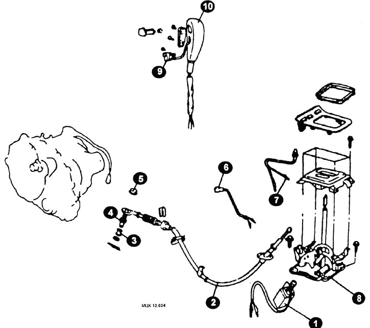
Gearbox controls
1 - shift lock solenoid; 2 - control cable; 3 - bushing; 4 - adjusting bolt; 5 - nut; 6 - Parking position switch; 7 - Position indicator light connector; 8 - gear shift lever assembly; 9 - Overdrive switch connector; 10 - gear shift lever handle.
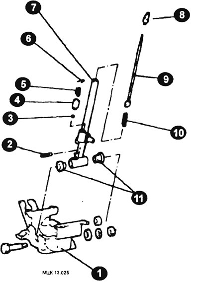
Typical elements of a gear shift lever
1 - bracket assembly; 2 - pin; 3 - ball; 4 - ball joint; 3 - spring; 6 - pin; 7 - lever assembly; 8 - valve stem adjusting sleeve; 9 - rod; 10 - spring; 11 - bushing.
Removal
After unscrewing the drain plug, drain the fluid from the gear plug.
Remove the air cleaner.
Remove the control cable.
Disconnect the speedometer sensor connector.
Disconnect the connectors from the pulse generator, transmission shift switch, downshift servo switch, solenoid, and oil temperature sensor.
Remove the starter.
Remove the anti-roll bar, disconnect the ends of the steering rod, remove the lower ball joint arm, and the lower axle shaft cover.
Remove the transmission cone housing cover.
Disconnect the oil cooler hose
CAUTION: Plug the ends of the oil cooler hoses and the transmission openings to prevent fluid leakage.
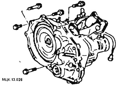
After unscrewing the mounting bolts (Figure MCK13.026), remove the automatic transmission.
Installation
The gearbox is installed in the reverse order, taking into account the following.
Before installation, secure the torque converter (1) on the gearbox side (Figure MCK13.027).
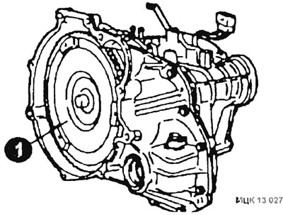
CAUTION: If the torque converter is initially installed on the engine, damage to the oil seal on the gearbox side may occur. Therefore, install the torque converter on the gearbox first.