



Warning! Remember that the dust generated during operation of the brake mechanisms may contain asbestos, which is extremely harmful to human health. Never blow off dust with compressed air or inhale it - wear a protective mask or respirator when servicing the mechanisms. Never use gasoline or petroleum-based solvents to wipe brake system components - use only branded cleaning agents or methyl alcohol!
Mirage models from 1993, Diamante and Galant
Braking mechanisms of the front and rear wheels
Note: The procedure below is the same for both front and rear disc brakes.
Removal
1. Jack up the car and place it on supports.
2. Remove the appropriate wheel.
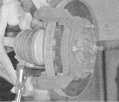
3. Remove the caliper, brake pads (see Section Replacing disc brake pads) and an anchor bracket.
 | 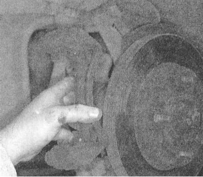 |
4. Without disconnecting the hydraulic hose, tie the caliper to the suspension elements with wire - make sure that the flexible brake hose is not stretched.
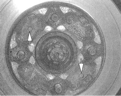
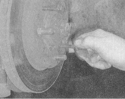
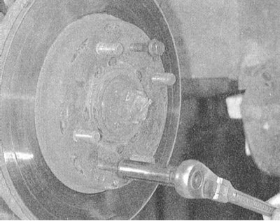
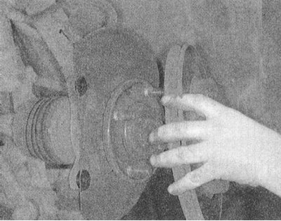
5. On some models, the brake disc is attached to the wheel hub with two small screws - unscrew the screws and remove the disc. If the disc is "stuck" and cannot be removed, screw a pair of suitable bolts into the threaded holes provided in the disc body and, gradually tightening them, release the disc.
 |  |
 |  |
Examination
1. Using a micrometer, measure the disc thickness at eight different points on its surface at approximately 45° intervals and at a distance of approximately 10 mm from the outer edge of the assembly. The minimum permissible disc thickness is 22.4 mm (for front brake mechanisms) / 8.4 mm (for rear mechanisms), the deviation should not exceed 0.015 mm.
2. A disc worn below the permissible limit must be replaced.
3. If variations exceeding the norm are detected, have the disk re-machined.
Note: As a result of turning, the thickness of the restored disk should not be below the minimum permissible limit (see above).
Installation
1. Install the disc on the hub, screw in and tighten the mounting screws.
2. Install the anchor bracket and brake shoes.
3. Install the caliper in place, screw in and tighten the guide pins.
4. Install the wheel, lower the vehicle to the ground and tighten the wheel nuts.
5. Before operating the vehicle, depress the brake pedal several times to seat the brake components.
Mirage models up to 1992.
Front wheel brakes
Removal
1. Without lifting the wheels off the ground, with the brakes applied, loosen the hub nut.
2. Jack up the car and place it on supports.
3. Remove the appropriate wheel.
4. Remove the hub nut and lock washer.
5. Remove the brake caliper and, without disconnecting the brake hose, tie the assembly with wire to the suspension element - make sure that the flexible brake hose is not stretched.
6. Remove the brake pads.
7. Release the lower control arm ball joint and tie rod end from the steering knuckle assembly.
8. Using a puller, release the drive shaft from the hub assembly.
9. Remove the lower mounting bolts and remove the suspension strut.
10. Unscrew the mounting bolts and remove the brake mechanism anchor bracket.
11. To separate the brake disc from the hub, unscrew the mounting bolts and use the MB991001 type tool.
Examination
1. Using a micrometer, measure the disc thickness at eight different points on its surface at approximately 45° intervals and at a distance of approximately 10 mm from the outer edge of the assembly. The minimum permissible disc thickness is 22.4 mm (for front brake mechanisms) / 8.4 mm (for rear mechanisms), the deviation should not exceed 0.015 mm.
2. A disc worn below the permissible limit must be replaced.
3. If variations exceeding the norm are detected, have the disk re-machined.
Note: As a result of turning, the thickness of the restored disk should not be below the minimum permissible limit (see above).
Installation
1. Install the brake disc onto the hub. Tighten the mounting nuts to the required torque (54 Nm) and install the assembly onto the vehicle.
2. Install the washer (chamfer facing outwards), screw on and temporarily tighten the hub nut.
3. Fasten the lower suspension arm ball joint and steering rod end to their standard locations.
4. Install the brake components.
5. Install the wheel and lower the car to the ground.
6. Apply the foot brake and tighten the hub nut to the required torque (260 Nm). Insert a new cotter pin and firmly bend its "antennae".
Front wheel brakes
Removal
1. Jack up the car and place it on supports.
2. Remove the appropriate wheel.
3. Disconnect the parking brake drive from the caliper.
4. Remove the caliper, brake pads and anchor bracket.
5. Without disconnecting the brake hose, tie the assembly to the suspension element with wire - make sure that the flexible brake hose is not stretched.
6. Remove the brake disc from the hub assembly.
Examination
1. Using a micrometer, measure the disc thickness at eight different points on its surface at approximately 45° intervals and at a distance of approximately 10 mm from the outer edge of the assembly. The minimum permissible disc thickness is 22.4 mm (for front brake mechanisms) / 8.4 mm (for rear mechanisms), the deviation should not exceed 0.015 mm.
2. A disc worn below the permissible limit must be replaced.
3. If variations exceeding the norm are detected, have the disk re-machined.
Note: As a result of turning, the thickness of the restored disk should not be below the minimum permissible limit (see above).
Installation
1. Place the disc on the hub and temporarily secure it with a pair of wheel nuts.
2. Install the anchor bracket and place the brake pads into it.
3. Install the caliper onto the bracket. Once the caliper is secured, the two temporary wheel nuts can be removed.
4. Connect the parking brake drive to the caliper.