
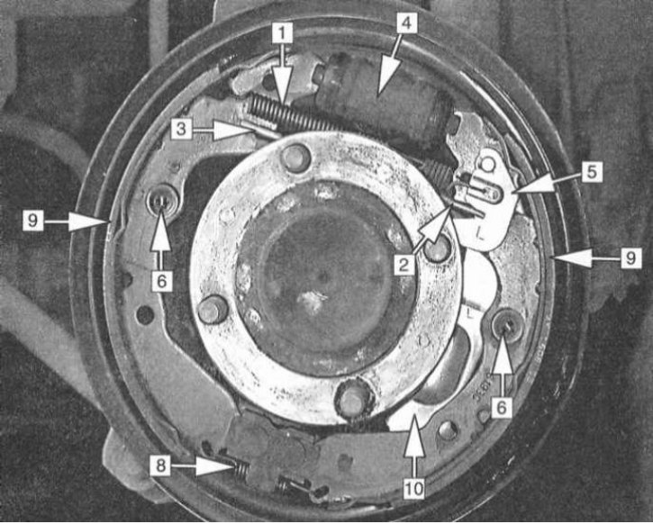
Typical drum brake design
1 - Spring fastening the shoe to the regulator lever; 2 - Upper coupling spring; 3 - Assembling the regulator; 4 - Wheel cylinder; 5 - Regulator lever; 6 - Guide springs; 7 - Anchor fingers of guide springs; 8 - Lower coupling spring; 9 - Brake shoes; 10 - Executive lever of the parking brake drive

A typical drum brake design is shown in the illustration.
Two shoes equipped with friction linings are mounted on a fixed brake shield. The shoes are enclosed within a drum that rotates with the wheel assembly. The shoes are fixed in their seats by means of springs, which provides them with a certain degree of movement with the possibility of pressing against the working surface of the drum. The shoes are pressed against the drum due to the force developed by the pistons of the wheel cylinder when the driver depresses the foot brake pedal. Pressing the surface of the friction linings against the walls of the drum, the shoes prevent its rotation, as a result of which the process of braking the vehicle is carried out. When the pressure in the hydraulic path is relieved, the shoes, due to the force developed by the coupling springs, return to their original position, depressing the pistons and releasing the drum.
Modern drum brake mechanisms are equipped with self-adjusters that compensate for wear of friction linings. Regulators work automatically at braking of the car moving a backing.
Note. On some models, self-adjusters are triggered every time the vehicle is braked.