English Русский
Български
Беларускі
Український
Српски
Hrvatski
Română
Polski
Slovenský
Magyar
Articles Bookmark Contacts Sitemap   
Company Audi Company Ford Company Hyundai Company Kia Company Mazda Company Mercedes-Benz Company Nissan
MitsubishiMan.ru


Home Colt Lancer Galant L200 Outlander Pajero Others
Galant 6 and 7 (1987-1998) Galant 5 (1983-1989, petrol)

Removal, restoration and installation of wheel cylinders (Mitsubishi Galant 6)

  • Home
  • Galant
  • 6 (1987-1998)
  • Chassis and running gear
  • Brake system
  • Removal, restoration and installation of wheel cylinders
0
Contents: Removal ⤓ Restorative repair ⤓ Installation ⤓


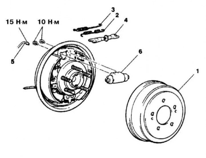
Wheel cylinder installation details for drum brake mechanism (Galant models)
1 - Brake drum; 2 - Spring for fastening the shoe to the adjusting lever; 3 - Upper tension spring; 4 - Assembling the automatic regulator; 5 - Brake pipe; 6 - Wheel cylinder


Removal


1. The installation details of the wheel cylinder of the drum brake mechanism are shown in the illustration.

2. Jack up the car and place it on supports.

3. Remove the spring that secures the shoe to the adjusting lever.

4. Remove the upper tension spring.

5. Remove the automatic regulator assembly.

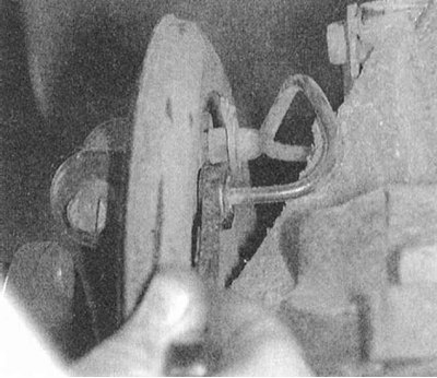
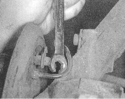
6. Prepare a drain container and disconnect the brake pipe from the wheel cylinder.

Attention! To loosen the union nut, in order to avoid rounding the corners of its splines, use a special open-end wrench with a split head - be prepared to collect any spilled liquid!


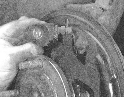
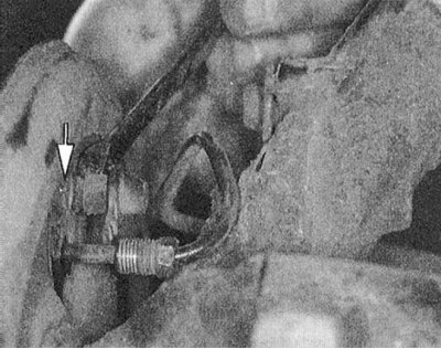
7. Remove the mounting bolts and remove the wheel cylinder assembly from the brake shield.


Restorative repair


1. The authors of this Manual recommend that vehicle owners avoid, if possible, the restoration of brake components, giving preference to replacing worn-out units.

2. If there are no replacement components at hand, the wheel cylinder can be repaired as described below.

3. First of all, you should take care to minimize the risk of dirt getting into the hydraulic tract of the brake system. Use only clean brake fluid to add to the system - if necessary, flush the entire brake tract, fill it with fresh fluid and bleed it.

4. Remove the wheel cylinder from the brake shield and transfer it to a clean workbench.
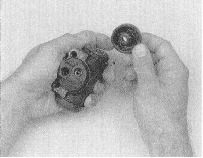


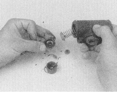
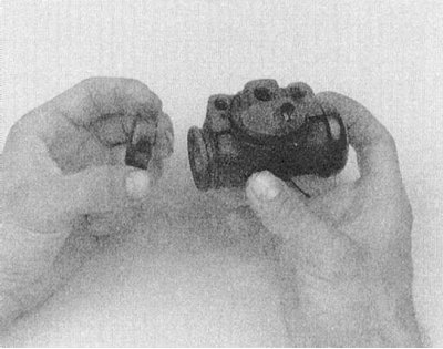
5. Remove the dust boots and release the pistons from the cylinder.

Note: When assembling the cylinder, the dust boots must be replaced without fail. Prepare a repair kit.


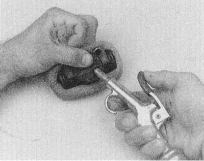
6. The wheel cylinder pistons are equipped with sealing cuffs and are expanded by a spring located between them. Remove all components from the cylinder assembly - use compressed air if necessary. If there is no access to a source of compressed air, be especially careful and try not to damage the cylinder mirrors when removing components. All components included in the repair kit are subject to replacement.

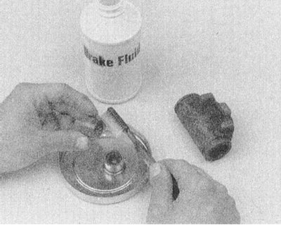
7. Thoroughly wash all metal components, including the cylinder body, with denatured alcohol or clean brake fluid.

Attention! Never use gasoline, kerosene, solvents or other petroleum products to flush brake components, as they can cause destruction of rubber sealing components.
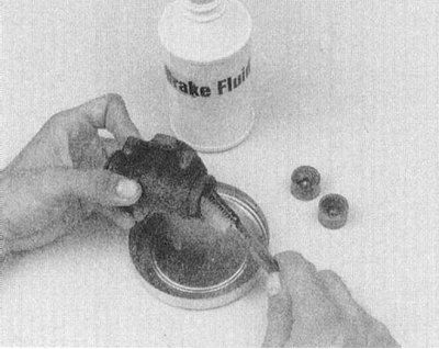


8. Dry all parts thoroughly (using compressed air if possible) - to avoid lint getting inside the cylinder, do not use rags to dry the components.


9. Carefully inspect the working surfaces of the cylinders. If scratches, scoring or other mechanical defects are detected, replace them.
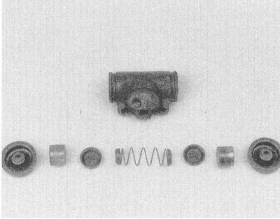


10. Lay out the prepared components in the order of their installation in the cylinder assembly.
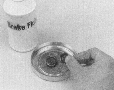


11. Lubricate the cylinder mirrors and piston seals with clean brake fluid.

12. Install the inner seals, then insert the pistons into the cylinder.
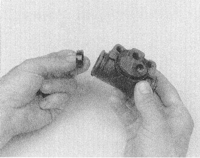


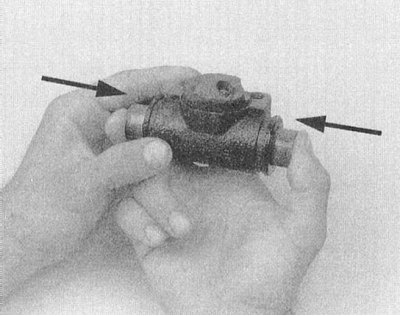
13. Manually, without using any tools, seat the anthers into the receiving grooves.


Installation


1. Install the cylinder in its regular place on the brake mechanism shield. Screw in the mounting bolts and tighten them to the required force (10 N·m).

2. Connect the brake line to the cylinder by tightening the union nut of its union connection with a force of 15 Nm.

3. Add fresh brake fluid to the master cylinder reservoir and loosen the bleed valve of the wheel cylinder being installed - the fluid will begin to fill the cylinder, which will reduce the time spent later on bleeding the circuit.

4. Install the automatic regulator assembly.

5. Install the upper tension spring.

6. Install the shoe mounting spring to the regulator lever.

(The material is based on data from the website: mitsubishiman.ru)

7. Install the brake drum.

8. Install the wheel, lower the vehicle to the ground and bleed the brake circuit (see Section Bleeding the brake system).
This article is available at: russian, bulgarian, belarusian, ukrainian, serbian, croatian, romanian, polish, slovak, hungarian
This article was reviewed by: Dmitry Vasiliev
Share with friends:
◀ Previous
Galant 6 and 7: Brake system
Next ▶

Adjustment of drum brake mechanisms
Removal and installation brake shoes
Checking the condition of the brake shoes
Removal, installation and inspection of the brake drum
Drum brakes — general information
Removal and installation the parking brake cable(s)
Adjusting the parking brake
Removal and installation parking brake friction shoes (with disc brakes)
Anti-lock Brake System (ABS) — Information, Diagnostics and Trouble Codes
Removal and installation of the hydraulic modulator
Similar materials for other Mitsubishi models

➤ Gearbox, wheel drive — external inspection for tightness Mitsubishi Colt 4 and 5 (1991-2003)
➤ Gearbox / Wheel drive Mitsubishi Lancer 3 and 5 (1984-1992)
➤ Checking tire wear and wheel alignment Mitsubishi L200 4 (2005-2014, diesel)
➤ Locking and unlocking the steering wheel Mitsubishi Outlander 1 (2003-2008)
➤ Replacing a damaged wheel Mitsubishi Pajero 1 and 2 (1982-1999)
➤ Steering wheel adjustment Mitsubishi Carisma (1995-2004)
Link in different formats to this article
Comments and feedback from visitors
No comments yet


Add up two numbers 12 + 10


Galant 6 and 7 (1987-1998) 
  • General information
  • Introduction to guide
  • User manual
  • Driving and operation
  • Maintenance
  • Power unit
  • Dismantling the engine
  • Engine overhaul
  • Cooling and heating
  • Power and exhaust systems
  • Engine electrical equipment
  • Engine management systems
  • Transmission
  • Mechanical gearbox
  • Automatic gearbox
  • Clutch
  • Drive shafts and transfer case
  • Chassis and running gear
  • Brake system
  • Car suspension
  • Steering
  • Body and interior
  • Exterior (external elements)
  • Interior (internal elements)
  • Doors, locks and windows
  • Electrical equipment
  • Equipment and devices
  • Wiring diagrams Galant
  • Wiring diagrams Mirage
  • Wiring diagrams Diamante
Galant 5 (1983-1989, petrol) 
  • General information
  • Troubleshooting
  • Maintenance
  • Power unit
  • Engine repair
  • Engine overhaul
  • Cooling and heating
  • Fuel and exhaust system
  • Engine electrical equipment
  • Reducing exhaust toxicity
  • Transmission
  • Manual gearbox
  • Automatic gearbox
  • Clutch and drive shafts
  • Chassis and running gear
  • Brake system
  • Car suspension
  • Steering
  • Body and interior
  • Exterior (external elements)
  • Interior (internal elements)
  • Doors, locks and windows
  • Electrical equipment
  • Equipment and devices
  • Electrical diagrams
MitsubishiMan.ru © 2018–2026 • Mobile version • Articles about Mitsubishi • Contacts • Sitemap: EN BG BY UA RS HR RO PL SK HU • Site search • Bookmark
Colt 2 and 3 (1983-1993) · Colt 4 and 5 (1991-2003) · Colt 5 (1995-2003) · Lancer 3 and 5 (1984-1992) · Lancer 9 (2000-2007) · Galant 5 (1983-1989) · Galant 6 and 7 (1987-1998) · L200 4 (2005-2014) · Outlander 1 (2003-2008) · Pajero 1 and 2 (1982-1999) · Pajero 4 (2006-2021) · Carisma (1995-2004) · Space Star (1998-2005) ·
This resource sets cookies 🍪 to avoid bothering you with repeated data entry.