
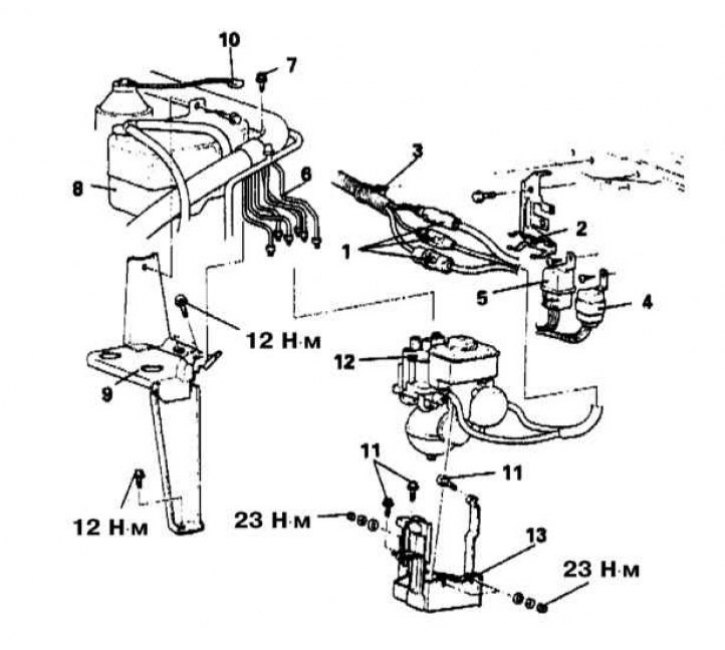
Installation details of hydraulic modulator assembly on Diamante models
1 - Electrical wiring connectors; 2 - Support bracket for wiring harness; 3 - Bandage; 4 - Electric motor relay; 5 - Valve relay; 6 - Brake tube; 7 - Coupling bolt of the clamp for fastening the A/C line; 8 - Condenser tank; 9 - Tank support bracket; 10 - Pin connector for electrical wiring of the hydraulic fluid level sensor of the 4WS system; 11 - Bolt; 12 - Hydraulic modulator; 13 - Modulator support bracket
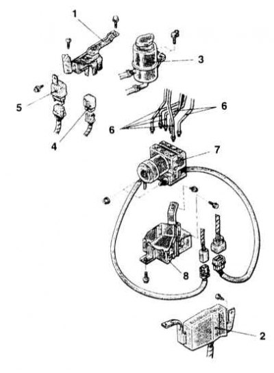
Installation details of hydraulic modulator assembly on Mirage models
1 - Support bracket; 2 - Mounting block of the K/V relay; 3 - Oil tank; 4 - Electric motor relay; 5 - Valve relay; 6 - Brake tube; 7 - Hydraulic modulator (HCU); 8 - HCU support bracket
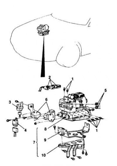
Installation details of hydraulic modulator assembly on Galant models
1 - Fittings for connecting brake pipes; 2 - Contact connectors for electrical wiring; 3 - Electric motor relay; 4 - Valve relay; 5 - Brake hoses; 6 - Support brackets; 7 - HCU assembly; 8 - Modulator; 9 - Support bracket A; 10 - Support bracket B
Attention! Brake fluid is one of the aggressive chemical compounds and, in contact with body panels, destroys the paintwork. Before proceeding with the procedure, cover the wings and front panel of the car with special covers, or just old blankets.
hydraulic modulator (HCU) is placed in the engine compartment of the car and includes a set of solenoid valves and an electric pump (with built-in motor). The pump provides the necessary pressure increase in the hydraulic system. The modulator cannot be repaired and must be replaced as an assembly in case of failure.
Diamante Models
Removing
1. The installation details of the hydraulic modulator assembly on Diamante models are shown in the illustration.
2. Disconnect the negative cable from the battery.
Attention! If the stereo system installed in the car is equipped with a security code, before disconnecting the battery, make sure that you have the correct combination to activate the audio system!
3. Remove the lower splash guard of the engine compartment.
4. Using a syringe or a rubber bulb, pump out as much hydraulic fluid as possible from the GTZ reservoir.
5. Remove and, without disconnecting the electrical wiring, move the relay mounting block to the side.
6. Remove the air intake sleeve.
7. Having previously marked, disconnect the brake lines from the hydraulic modulator - get ready to collect the spilled liquid. Seal the open ends of the tubing immediately to prevent dirt and moisture from entering the system.
Note. When releasing the union nuts, the relay mounting block will have to be moved as far as possible to the side.
8. Disconnect the electrical wiring from the hydraulic modulator.
9. Disconnect the modulator ground bus from the chassis.
10. Turn out three fixing bolts and remove the modulator in gathering with a basic arm.
Note. The modulator has a significant weight and at this stage it would be wise to use the help of an assistant. Place the removed assembly on the workbench in a vertical position. Do not subject the modulator to shock loads!
11. Loosen the mounting nut and remove the support bracket from the modulator assembly.
12. Disconnect the ground bus from the bracket.
Installation
1. If removed, install the support bracket onto the hydraulic modulator assembly.
2. Connect the ground bar to the bracket.
3. Install the modulator assembly in its regular place - try to keep it vertical all the time.
4. Screw on the fixing nuts and tighten them firmly.
5. Connect the electrical wiring to the modulator.
6. Loosely connect the hydraulic lines to your fittings on the modulator assembly (pay attention to the markings applied during dismantling). Tighten the male connectors of each line with the required torque (15 Nm).
7. Fill in the reservoir with fresh brake fluid, bringing its level to the MAX mark.
8. Bleed the brake path (first GTZ, then alternately each of the circuits - see Section Bleeding the brake system).
9. Replace the relay mounting block and air intake sleeve.
10. Install splash screens.
Models Galant and Mirage
Removing
1. The installation details of the hydraulic modulator assembly on the Galant and Mirage models are shown in the illustrations.
2. Using a syringe or a rubber bulb, pump out as much hydraulic fluid as possible from the GTZ reservoir.
3. Remove the left front wheel arch protection locker.
4. Remove the expansion tank of the cooling system (see chapter Cooling and heating systems).
5. Remove the expansion tank support bracket.
6. Remove the dust shield installed under the hydraulic modulator assembly.
7. Once marked, disconnect the hydraulic hoses and tubes from the HCU. Plug the open ends of the lines immediately to prevent dirt and moisture from entering the system.
8. Remove the cover from the relay mounting block and disconnect the electrical wiring from the modulator assembly.
9. Turn out bolts of fastening of three basic arms, lower assembly HCU down and remove it from the car.
Note. The modulator has a significant weight and at this stage it would be wise to use the help of an assistant. Place the removed assembly on the workbench in a vertical position. Do not subject the modulator to shock loads!
10. If necessary, remove the relay and support brackets from the modulator assembly.
Installation
1. If removed, install support brackets and relays to the hydraulic modulator assembly. Tighten the fixing bolts to the required torque (22 Nm).
2. Install the HCU in its proper place - try to keep the assembly upright at all times.
3. Screw in the mounting bolts and tighten them with the required force (22 Nm).
4. Connect the electrical wiring to the modulator.
5. Install the cover on the relay mounting block.
6. Connect the hydraulic lines to your fittings on the modulator assembly (pay attention to the markings applied during dismantling). Tighten the male connectors of each line with the required torque (13 Nm).
7. Fill in the reservoir with fresh brake fluid, bringing its level to the MAX mark.
8. Bleed the brake system (see Section Bleeding the brake system).
9. Reinstall the dust screen and expansion tank of the cooling system with its bracket.
10. Install the wheel arch protection locker.
11. Turn on the ignition and check that the ABS warning lamp on the instrument panel is working properly.
12. Carry out a road test of the car.