



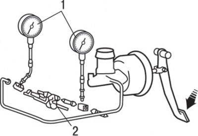
Fig. 14.5. Connecting pressure gauges to the input and output of the pressure regulator respectively: 1 – pressure gauge; 2 – pressure regulator
1. Connect two pressure gauges to the inlet and outlet of the pressure regulator respectively, as shown in Fig. 14.5.
2. Bleed the brake hydraulic system and pressure gauges.
3. While gradually depressing the brake pedal, take the following measurements and make sure that the measurement results are within the tolerance.
Check that the outlet pressure begins to drop relative to the inlet pressure (turn-on point).
Nominal pressure value, MPa:
- 3.43±0.25 (engine 1600);
- 3.92±0.25 (engine 1800).
Check and ensure that when the brake pedal pressure increases, the fluid pressure at the outlet is within the specified limits, while the pressure at the inlet is 9.81 MPa.
Nominal value of pressure at the regulator outlet, MPa:
- 5.03±0.4 (engine 1600);
- 5.39±0.4 (engine 1800).
The difference in pressure at the outlet between the right and left circuits of the hydraulic system must be no more than 0.8 MPa.
If the pressure measurements are not within the specified limits, replace the rear brake pressure regulator.