Contents: Removal ⤓ Examination ⤓ Disassembly ⤓ Replacing the hub bolt ⤓ Examination ⤓ Assembly ⤓ Installation ⤓
Removal
Note:
- - The parts are removed in the order of numbers shown in the figure "Removing the front wheel hub".
- - When removing parts, pay attention to the following operations.
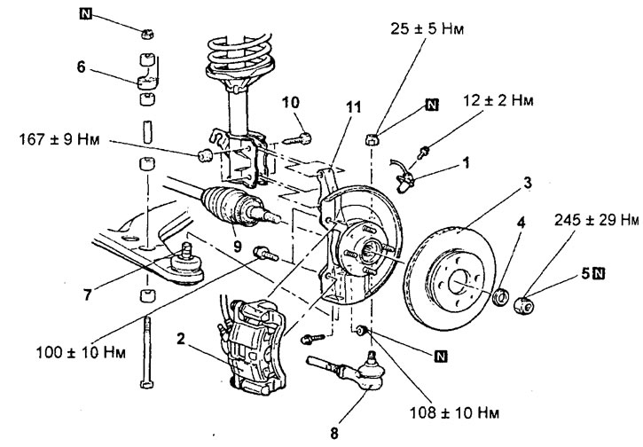
Removal the front wheel hub. 1 - Front wheel speed sensor (models with ABS), 2 - Brake caliper, 3 - Brake disc, 4 - Washer, 5 - Drive shaft mounting nut, 6 - Anti-roll bar connection, 7 - Lower arm ball joint connection, 8 - Tie rod end, 9 - Drive shaft, 10 - Front suspension strut mounting bolt, 11 - Front steering knuckle and hub.
Caution: (models with ABS) Be careful not to damage the wheel speed sensor rotor.
1. Remove the brake caliper assembly.
Note: Temporarily suspend the brake caliper from the frame with wire without disconnecting the brake hose.
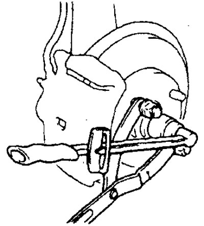
2. Loosen the drive shaft nut as shown in the figure.
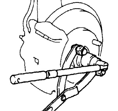
3. Disconnect the ball joint of the lower suspension arm from the steering knuckle.
Attention:
- - To prevent the puller from bouncing off, it is necessary to first tie it with a cord to the suspension strut or other nearby part of the car.
- - Loosen the mounting nut on the ball joint pin at the steering knuckle without unscrewing it.

4. Remove the drive shaft.
Examination
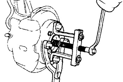
1. Check the hub for cracks and signs of increased wear on the splines.
2. Check the oil seal for damage.
3. Check the steering knuckle for cracks.
4. Check the hub bearing for damage.
Note: If there is play in the connection between the steering knuckle and the outer bearing race, or the hub and the inner bearing race, the bearing or damaged parts must be replaced.
Disassembly
Note: The hub is disassembled in the order of the numbers shown in the figure "Disassembling and assembling the front wheel hub". When removing parts, pay attention to the following operations.
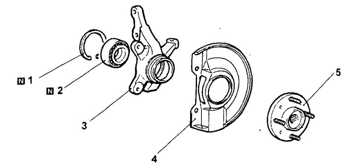
Disassembling and assembling the front wheel hub. 1 - retaining ring, 2 - hub bearing, 3 - steering knuckle, 4 - dust cover, 5 - hub.
1. Remove the hub from the steering knuckle.
Caution: When removing the hub, replace the hub bearing with a new one.
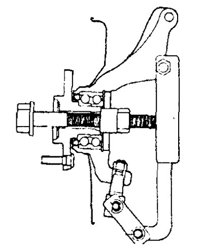
2. Remove the hub bearing.
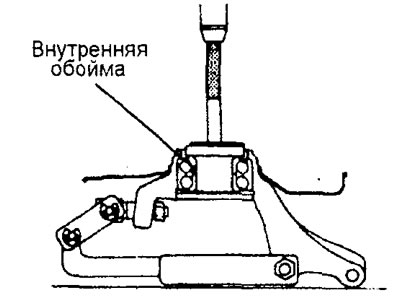
a) To grasp the outer part of the inner race using a special tool, it is necessary to break the outer seal in two places, as shown in the figure.
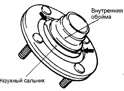
b) Using a special tool, remove the inner bearing race (outer part) from the hub.
Caution: When removing the inner bearing race, it is necessary to hold the hub to prevent it from falling.
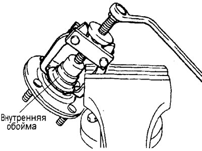
c) Install the outer part of the inner race removed from the hub as shown in the figure, then, using a special tool, remove the bearing.
Replacing the hub bolt
1. Remove the brake caliper and brake disc.
2. Using a special tool, remove the hub bolt.
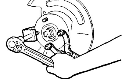
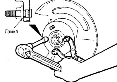
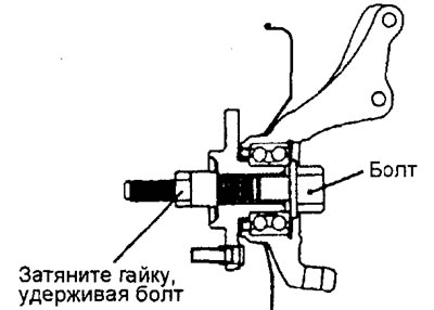
3. Using the hub bolt nut, install the new hub bolt as shown in the illustration.
Examination
1. Clean the mounting surfaces of the brake disc and wheel hub for signs of fretting corrosion (corrosive wear) and contamination.
2. Check the inner surface of the steering knuckle for corrosion and cracks.
3. Check the bearing for defects.
Assembly
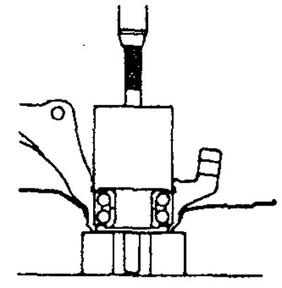
1. Using a special tool, press the bearing into the steering knuckle.
Note: The pressing force is applied to the outer bearing race.
2. Install the retaining ring into the steering knuckle.
3. Install the outer oil seal.
4. Install the dust cover onto the steering knuckle.
5. Install the wheel hub onto the steering knuckle.
6. Check the moment of release of the hub bearing.
a) Using a special tool, install the hub into the steering knuckle.
b) Tighten the special tool nut.
Tightening torque: 245 ±29 Nm
c) Rotate the hub to properly install the bearing.
d) Using a special tool, measure the value of the hub bearing breakaway torque.
The maximum permissible value is 1.8 N·m or less
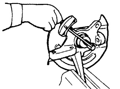
d) The value of the hub bearing breakaway moment must be within the specified limits. In addition, the bearing rotation must be uniform, without jamming or vibration.
7. Checking the axial clearance of the hub bearing.
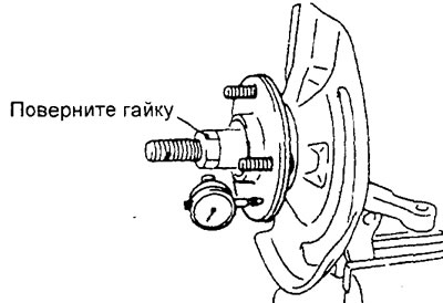
a) Measure the axial clearance of the hub bearing.
The maximum permissible value is 0.05 mm
b) If, when tightening the fastening nut to a torque of 245±29 N·m, the breakaway torque and axial clearance of the hub bearing are not within the specified limits, this is probably the result of incorrect installation of the bearing, hub, or incorrect assembly of these parts with the steering knuckle. In this case, replace the bearing, repeat the operation of installing the bearing in the hub.
8. Install the inner seal.
Installation
Note: Installation is performed in the reverse order of removal. When installing parts, pay attention to the following operations.
1. Installing the anti-roll bar mounting nut.
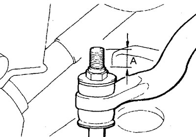
Tighten the nut so that the length (A) of the protruding part of the stabilizer mounting bolt corresponds to the nominal value.
Nominal value (A) - 22±1.5 mm
2. Install the drive shaft mounting nuts.
a) Make sure the drive shaft washer is installed correctly as shown in the figure.
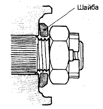
b) Using the special tool, tighten the drive shaft mounting nut.
Tightening torque - 245±29 N
Caution: The front wheel hub bearing must not be loaded with the weight of the vehicle before tightening the drive shaft mounting nut.