



Removal
To remove the front wheel hub, perform the following operations in sequence.
1. Loosen the front wheel mounting bolts. Apply the parking brake, then raise the front of the vehicle and secure it on stands. Remove the appropriate front wheel.
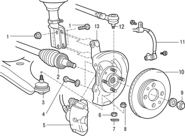
Fig. 15.3. Front wheel hub: 1 – bolt and nut for fastening the steering knuckle to the suspension strut (108–127 N·m); 2 – drive shaft; 3 – connection of the ball joint pin of the lower arm with the steering knuckle; 4 – bolt (90–110 Nm); 5 – caliper assembly; 6 – nut (25 Nm); 7 – cotter pin; 8 – nut (67 Nm); 9 – drive shaft mounting nut (216–255 Nm); 10 – brake disc; 11 – Front wheel speed sensor (car with ABS); 12 – steering rod end connection; 13 – steering knuckle and hub
2. Remove sensor 11 (Fig. 15.3) of the front wheel speed (vehicle with ABS).
3. Unscrew the bolts and remove the front brake caliper 5 from the steering knuckle. Without disconnecting the brake hose from the caliper, tie the caliper to the body using soft wire. Do not stretch or twist the brake hose.
4. Remove the brake disc 10.
5. Using a special device to prevent the hub from turning, unscrew the drive shaft mounting nut.
6. Loosen the nut securing the lower arm ball joint pin to the front suspension strut. Using a puller, remove pin 3 of the ball joint from the front suspension strut.
7. Remove cotter pin 7 securing the steering tip mounting nut.
8. Using a special tool, loosen nut 6 securing the steering rod end. The nut should be loosened, but not completely unscrewed. To prevent the puller from slipping off, tie it with a rope or wire beforehand. Use the puller to push the ball joint out of the steering rod end and completely unscrew the nut.
9. Remove the outer end of drive shaft 2 from the front wheel hub. Using soft wire, tie the end of the drive shaft to the body.
10. Loosen the nuts and remove the bolts 1 securing the steering knuckle to the suspension strut and remove the steering knuckle with the hub.
Caution! On vehicles with ABS, the protruding part of the wheel speed sensor tip must be handled with particular care to prevent it from hitting or being damaged by other parts.
Attention! On vehicles with ABS, when removing and installing the drive shaft, it is necessary to avoid damaging the rotor installed on the outer race of the Rzeppa (RJ) or Bierfeld (BJ) CV joint.
Examination
1. Check the hub for cracks and signs of increased wear on the splines.
2. Check if the oil seal is damaged
3. Check the steering knuckle for cracks.
4. Check if the hub bearing is damaged.
Attention! If there is play between the steering knuckle and the outer bearing ring or the hub and the inner bearing ring, the bearing or damaged parts must be replaced.
Installation
Installation is carried out in the reverse order of removal, taking into account the following.
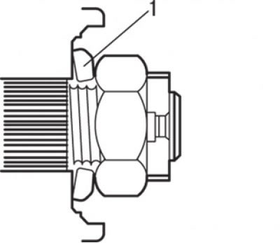
Fig. 15.4. Correct installation of the washer (1) under the drive shaft mounting nut
1. Correctly install the washer under the drive shaft nut (Fig. 15.4). Using a torque wrench, tighten the nut to the required torque, while holding the hub from turning with a special tool.
Caution: Before tightening the drive shaft nut, the front wheel hub bearing must not be under the force of gravity of the vehicle.
Disassembly
To disassemble the front wheel hub, perform the following operations.
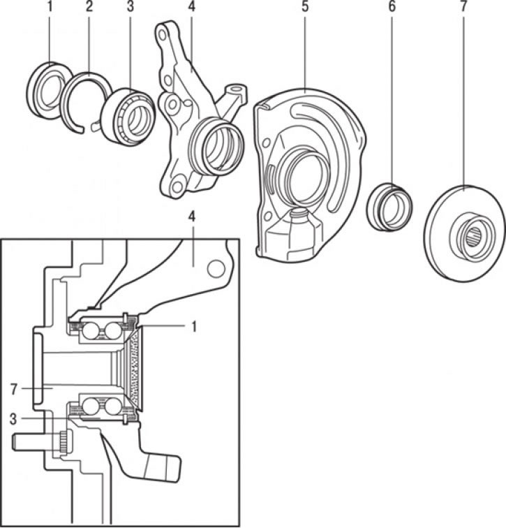
Fig. 15.5. Front wheel hub: 1 – inner seal; 2 – retaining ring; 3 – hub bearing; 4 – steering knuckle; 5 – mudguard; 6 – outer seal; 7 – hub
1. Remove the inner seal 1 (Fig. 15.5).
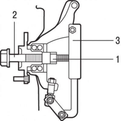
Fig. 15.6. Using special tools MB990998 (2), MB 991056 or MB 991355 (3) to remove the hub: 1 – nut
2. Using a special tool, remove the hub (Fig. 15.6).
Caution: When removing the hub, always replace the hub bearing with a new one.
3. Unscrew the two bolts and remove the mudguard 5 (see Fig. 15.5).
4. Remove the retaining ring 2 from the steering knuckle, which secures the outer bearing ring.
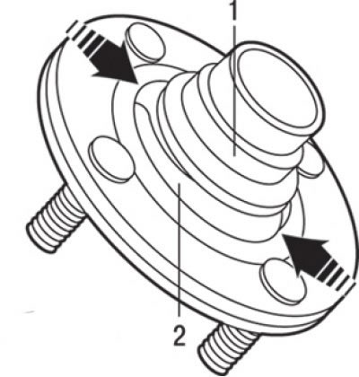
Fig. 15.7. Places of fracture of the outer seal: 1 – inner bearing ring; 2 – outer seal
5. Remove the hub bearing. To grasp the outer part of the inner ring using the jaws of a special puller, it is necessary to break the outer seal in two places (Fig. 15.7).
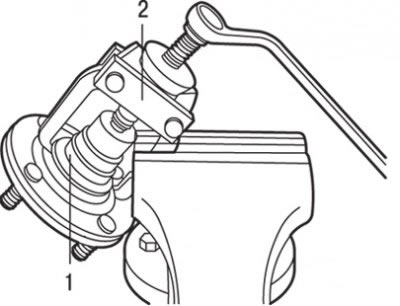
Fig. 15.8. Using the special puller MB990810 (2) to remove the inner ring (1) of the bearing from the hub
6. Using a special puller MB990810, remove the inner bearing ring (outer part) from the hub (Fig. 15.8).
Caution! When removing the inner bearing ring, hold the hub to prevent it from falling.
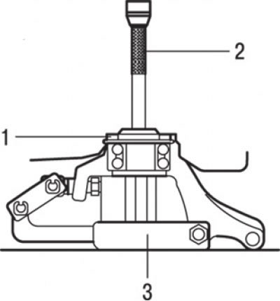
Fig. 15.9. Using a special puller to remove the bearing: 1 – inner bearing ring; 2 – special puller МВ990938 and МВ990932; 3 – special tool МВ991056 or МВ991355
7. Install the outer part of the inner ring removed from the hub into the bearing and then remove the bearing using a special puller (Fig. 15.9).
8. Remove the outer seal 6 (see Fig. 15.5).
Examination
1. Check the condition of the mating surfaces of the front hub and brake disc for signs of wear and contamination.
2. Check the condition of the inner surface of the steering knuckle for cracks and signs of wear.
3. Check the wheel hub bearing.
Assembly
Assembly is carried out in the reverse order of removal, taking into account the following.
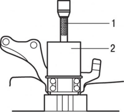
Fig. 15.10. Using special tools MB990883 (1) and MB990890 (engine 1800) or MB991050 (engine 1600) (2) to press the bearing into the steering knuckle
1. Install the hub bearing. Fill the bearing with universal grease. Apply a thin layer of grease to the mating surfaces of the steering knuckle and hub. Using special tools, press the bearing into the steering knuckle (Fig. 15.10).
Caution! The pressing force is applied to the outer ring of the bearing.
2. Install the retaining ring.
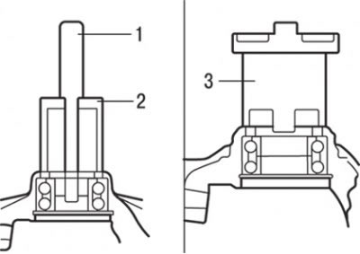
Fig. 15.11. Using the special mandrel MB990947 and MB990847 (1 and 2) for vehicles with 1800 engines and MB991387 (3) for 1600 vehicles to install the outer oil seal
3. Install the outer oil seal. Using the special mandrel MB990947 and MB990847 for vehicles with 1800 engines and MB991387 for 1600 vehicles, install the oil seal (from the hub side) into the steering knuckle flush with the end surface of the steering knuckle (Fig. 15.11). Apply universal grease to the working edge, inner and end surfaces of the oil seal that contact the hub.
4. Install the mudguard.
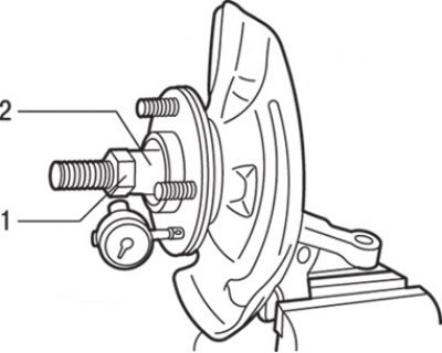
Fig. 15.12. Checking the axial clearance of the hub bearing: 1 – nut (216–255 N·m); 2 – device МВ990998
5. Install the hub. Using a dial indicator, measure the axial clearance of the hub bearing, for which purpose first secure the steering knuckle in a vice (Fig. 15.12). The maximum permissible value is 0.05 mm. If, when tightening the nut with a special tool to a torque of 216–255 N·m, the value of the start of rotation torque and axial clearance of the hub bearing are not within the specified limits, this is probably the result of incorrect installation of the bearing, hub and/or incorrect assembly of these parts with the steering knuckle. In this case, it is necessary to replace the bearing and reassemble the unit. Tighten the nut to a torque of 216–255 N·m.
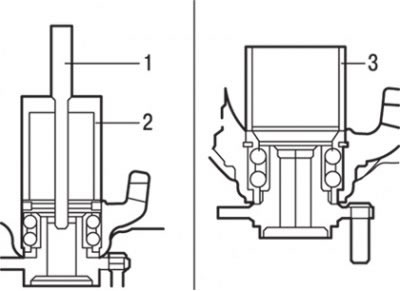
Fig. 15.13. Using the MB990883 and MB990890 (1 and 2) tools for vehicles with 1800 engines and MB991389 (3) for 1600 vehicles to install the inner oil seal in the steering knuckle
6. Install the inner seal. Apply universal grease to the back of the inner seal. Using tools MB990883 and MB990890 for vehicles with 1800 engines and MB991389 for vehicles with 1600 engines, install the inner seal into the steering knuckle until it contacts the retaining ring (Fig. 15.13). Apply a layer of grease to the working lip of the seal.