



Caution! To remove and disassemble the front suspension strut, you must use a ball joint puller and a spring compressor.
Disassembly
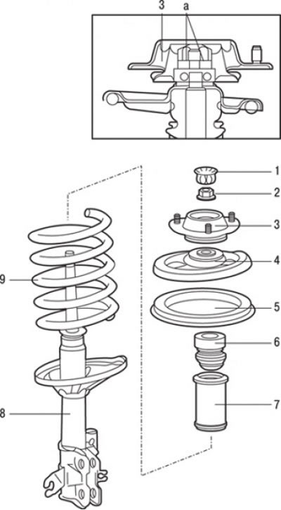
Fig. 15.25. Elements of the front suspension strut: a – place of application of lubricant; 1 – dust cover; 2 – self-locking nut (78 Nm); 3 – shock absorber support; 4 – upper spring cup; 5 – spring pad, upper; 6 – compression stroke buffer; 7 – protective cover; 8 – front strut assembly; 9 – spring
1. Remove dust cover 1 (Fig. 15.25).
2. Secure the front suspension strut and, using the special device MB991237 with the grips MB991238, compress the spring so that it moves away from the upper cup. When using the special device for compressing springs, make sure that the spring coils are securely gripped and compress the spring from opposite sides. The spring has a very high compression force, so use only a reliable tool. Never tie the spring with wire.
Install special tools symmetrically and in such a way that their maximum length does not exceed the installation limits.
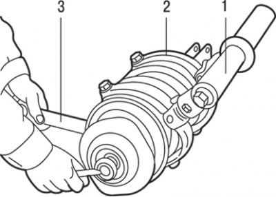
Fig. 15.26. Compressing the spring with the MB991237 device (1) with the MB991238 grips (2) and using the special key MB990278 or MB990775 (3) to loosen the self-locking nut of the front suspension strut
3. Holding the upper spring cup with a special key MB990278 or MB990775, loosen the self-locking nut (Fig. 15.26).
Caution: Do not use an impact wrench to loosen the self-locking nut.
4. Remove the damping support 3 (Fig. 15.25) of the rack.
5. Remove the upper cup 4 springs.
6. Remove the upper spring cover 5.
7. Remove the compression stroke buffer 6.
8. Remove the protective cover 7.
9. Remove spring 9.
Examination
1. Check the shock absorber for leaks of shock absorber fluid. Check the entire length of the shock absorber rod for pitting. Check the shock absorber body for mechanical damage. Set the shock absorber in a vertical position and check its operation by moving the shock absorber rod through its full stroke. The shock absorber rod should move smoothly, with noticeable resistance. If the shock absorber rod moves jerkily or there is mechanical damage, the shock absorber must be replaced.
2. Check the bearing located in the front strut damper support for wear or rust.
3. Check rubber parts for damage or deterioration in technical condition.
4. Check the spring for deformation, wear or damage.
Rack disposal
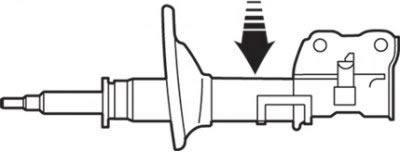
Fig. 15.27. Location of drilling a 3 mm diameter hole for the disposal of the front suspension strut
To dispose of a failed strut, lay it horizontally and extend the shock absorber rod to the stop. Then drill a hole with a diameter of about 3 mm in the place indicated by the arrow in Fig. 15.27 and release the gas.
Warning! The gas itself is harmless, but when it comes out of the hole, chips left after drilling may fly out, so be sure to wear safety glasses.
Assembly
Assembly is carried out in the reverse order of disassembly, taking into account the following.
1. After compressing the coil spring, use the special tool (MB 991237 and MB 991238) to pre-tighten the self-locking nut.
Caution: Do not use an impact wrench when tightening the special tool bolt.
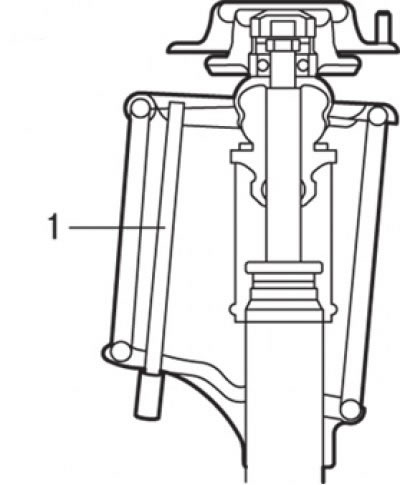
Fig. 15.28. Using a piece of pipe (1) to align the holes in the lower and upper support cups of the strut spring
2. Align the holes in the lower and upper spring support cups of the strut. This job is easily accomplished using a section of pipe as shown in Fig. 15.28.
3. Correctly align both end coils of the spring with the grooves in the upper and lower cups, then loosen the special spring compressor.
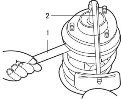
Fig. 15.29. Using the special tool MB990278 or MB990775 (1) and a torque wrench (2) to tighten the self-locking nut
[The article is reprinted from a web resource: MitsubishiMan.ru]
4. Using the special tool MB990278 or MB990775 and a torque wrench, tighten the self-locking nut to the required tightening torque (Fig. 15.29).
Warning! Do not use an impact wrench.
5. Apply general purpose grease to the front strut damper bearing.
Caution! When applying consistent grease, be careful not to allow grease to come into contact with the rubber elements of the damper support.