



Contents: Technical characteristics (coil…⤓ Checking and adjusting the front…⤓ Convergence ⤓ Divergence when turning ⤓ Camber, longitudinal and transverse…⤓ Checking the axial play of the lower…⤓ Checking the protective boot of the…⤓
Front suspension independent (MacPherson), telescopic, with hydraulic shock absorbers, with coil springs. Gas-filled shock absorber double action.
Technical characteristics (coil spring)
Basic data for adjustment and control
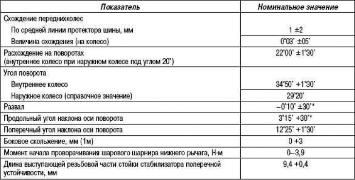
* The difference between the right and left wheels should not be more than 30'.
Lubricants

Checking and adjusting the front wheel alignment angles
Measure the wheel alignment angles using special equipment on a flat horizontal area. Before measuring the wheel alignment angles, the condition of the front suspension, steering, tires and wheels should be checked.
Convergence
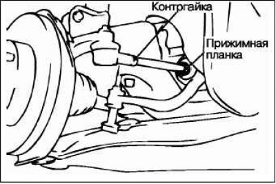
Adjust the front wheel alignment by removing the clamping bar and loosening the lock nut, rotating (in the opposite direction) the right and left tie rod turnbuckles by the same distance.
Caution! Toe-in is reduced if the left turnbuckle is rotated toward the front of the vehicle and the right turnbuckle is rotated toward the rear of the vehicle.
Install the clamping bar and tighten the wheel lock nut to the specified torque.
Nominal tightening torque: 40 + 5 Nm
Make sure the toe-in value is within the specified value.
Using a turning radius gauge, ensure that the turning angle is within the specified value.
Divergence when turning
To check the condition of the steering rods, especially for a vehicle that has been in an accident or is suspected of being in an accident, in addition to checking and adjusting the wheel alignment, it is also necessary to check the toe-in when turning.
This check must be performed for both left and right turns.
Camber, longitudinal and transverse angles of inclination of the steering axis
Attention! The camber and tilt angle of the steering axis are set at the manufacturer and do not require adjustment.
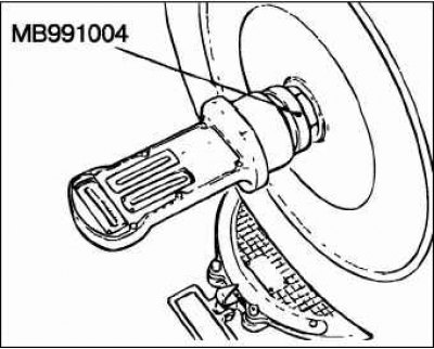
If the drive shaft nuts are loose, checking the wheel hub bearings is not permitted.
Caution! For vehicles with aluminum alloy wheels: Attach the wheel alignment gauge to the wheel drive shaft using the special tool (MB991004). Tighten the special tool to the same tightening torque of 245 ±29 N·m as the drive shaft nut.
Checking the axial play of the lower arm ball joint
Raise the car.
Disconnect the stabilizer bar link from the lower control arm.
By shaking the lever up and down with your hands, check for play in the axial direction of the ball joint. If there is significant play, replace the lower arm assembly.
Checking the protective boot of the lower arm ball joint
Use your fingers to squeeze the lower arm ball joint boot to ensure that there are no cracks or damage.
If there are cracks or damage to the ball joint protective boot, replace the lower arm assembly.
Attention! The presence of cracks or damage to the protective cover of the ball joint is usually accompanied by damage to the ball joint.